
Advertisements
Fuse box diagram (fuse layout), location, and assignment of fuses Volvo V60 Plug-in Hybrid (2014, 2015, 2016, 2017, 2018).

Checking and Replacing Fuses
The fuses help protect the vehicle’s electrical components from overloading. If an electrical component fails to function, this may be due to a blown fuse. The easiest way to see if a fuse is blown is to remove it.
To do so:
- Switch off the headlights, the ignition, and all electrical consumers.
- Open the appropriate fuse box.
- See diagrams below for details about which fuse to check.
- Pull the fuse straight out. If a fuse is difficult to remove, a special fuse removal tool is located on the inside of the engine compartment fuse box cover.
- From the side, examine the curved metal wire in the fuse to see if it is intact. If the wire is broken, insert a new fuse of the same color and amperage (written on the fuse).
- Replace the cover.
If fuses burn out repeatedly, have the electrical system inspected by a trained and qualified Volvo service technician.
Notice
- Never use metal objects or fuses with a higher amperage than those stated on the following pages. Doing so could seriously damage or overload the vehicle’s electrical system.
- Never repair fuses.
Location
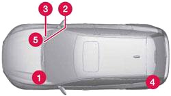
Central electrical unit locations in a left-hand drive car. In a right-hand drive car, the central electrical units under the glovebox change sides.
- Engine compartment
- Under the glovebox №1
- Under the glovebox №2
- Cargo area
- Engine compartment cold zone (only with Start/Stop)
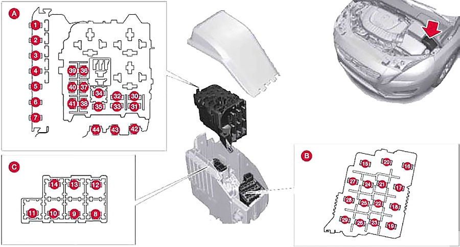
Engine Compartment Fuse Box
On the inside of the cover is a label that shows the location of the fuses.
| № | Function | A |
|---|---|---|
| 1 | - | - |
| 2 | Primary fuse for the central electronic module (CEM) under the glovebox | 50 |
| 3 | - | 60 |
| 4 | Primary fuse for relay/fuse box under the glovebox | 60 |
| 5 | - | - |
| 6 | - | - |
| 7 | - | - |
| 8 | 2014: Heated windscreen, lefthand side | 40 |
| 9 | Windscreen wipers | 30 |
| 10 | Parking heater | 25 |
| 11 | - | - |
| 12 | 2014: Heated windscreen, righthand side | 40 |
| 13 | ABS pump | 40 |
| 14 | ABS valves | 20 |
| 15 | Headlamp washers | 20 |
| 16 | Headlamp levelling, Active Xenon headlamps - ABL | 10 |
| 17 | Primary fuse for the central electronic module (CEM) under the glovebox | 20 |
| 18 | ABS | 5 |
| 19 | Speed related power steering | 5 |
| 20 | Engine control module, Transmission control module, Airbags | 10 |
| 21 | Heated washer nozzles | 10 |
| 22 | - | - |
| 23 | Headlamp control | 5 |
| 24 | - | - |
| 25 | - | - |
| 26 | - | - |
| 27 | Relay coils | 5 |
| 28 | Auxiliary lamps | 20 |
| 29 | Horn | 15 |
| 30 | Relay coil in main relay for engine management system, Engine control module | 10 |
| 31 | Transmission control module | 15 |
| 32 | - | - |
| 33 | Relay coils in central electrical unit in engine compartment cold zone, Relay coil in relay for coolant pump | 5 |
| 34 | Starter relay | 30 |
| 35 | Glow control module | 10 |
| 36 | Engine Control Module (ECM) | 15 |
| 37 | Mass air flow sensor, Control valves | 15 |
| 38 | Valves, Oil level sensor | 10 |
| 39 | Lambda-sonds; Control module, radiator roller cover | 15 |
| 40 | Diesel filter heater | 20 |
| 41 | 2014: Crankcase ventilation heater | 5 |
| 2015-2018: Crankcase ventilation heater | 10 | |
| 42 | Glow plugs | 70 |
| 43 | Cooling fan | 80 |
| 44 | Electro-hydraulic power steering | 100 |
Advertisements
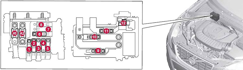
Cold Zone
| № | Function | A |
|---|---|---|
| A1 | Main fuse for central electrical unit in the engine compartment | 175 |
| A2 | Main fuse for central electronic module (CEM) under the glovebox, relay/fuse box under the glovebox, central electrical unit in cargo area | 175 |
| 1 | Vacuum pump for brake system | 40 |
| 2 | Primary fuse for the central electronic module (CEM) under the glovebox | 50 |
| 3 | Primary fuse for relay/fuse box under the glovebox | 60 |
| 4 | Primary fuse for central electrical unit B in cargo area | 50 |
| 5 | Primary fuse for central electrical unit A in cargo area | 60 |
| 6 | Ventilation fan | 40 |
| 7 | - | - |
| 8 | - | - |
| 9 | - | - |
| 10 | - | - |
| 11 | Oil pump automatic gearbox | 30 |
| 12 | - | - |
Behind the engine
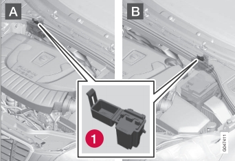
A: Left-hand drive car.
B: Right-hand drive car.
1 – 5A fuse “Monitoring of vacuum pump for brake system”.
Passenger Compartment Fuse Box
The fuses are located underneath the glove box.
Box №1 Diagram
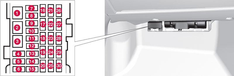
| № | Function | A |
|---|---|---|
| 1 | Primary fuse for audio control module, Primary fuse for fuses 16-20 | 40 |
| 2 | 2015-2018: Windscreen washers; Rear window washer | 25 |
| 3 | - | - |
| 4 | - | - |
| 5 | - | - |
| 6 | Door handles, keyless system | 5 |
| 7 | - | - |
| 8 | Control panel, driver's door | 20 |
| 9 | Control panel, front passenger door | 20 |
| 10 | Control panel, rear passenger door, right | 20 |
| 11 | Control panel, rear passenger door, left | 20 |
| 12 | Keyless | 7.5 |
| 13 | Power seat driver's side | 20 |
| 14 | Power seat passenger side | 20 |
| 15 | 2014: Windscreen washers, Rear window washer | 25 |
| 16 | Infotainment Control Module or Screen | 5 |
| 17 | Audio control module, TV, Digital radio | 10 |
| 18 | Audio control module or Control module Sensus | 15 |
| 19 | Telephone, Bluetooth | 5 |
| 20 | - | - |
| 21 | Sun roof, interior lighting roof, climate sensor, damper motors air intake | 5 |
| 22 | 12 V socket, tunnel console | 15 |
| 23 | Seat heating, rear passenger side right | 15 |
| 24 | Seat heating, rear passenger side left | 15 |
| 25 | Electric additional heater | 5 |
| 26 | Seat heating, front passenger side | 15 |
| 27 | Seat heating, front driver's side | 15 |
| 28 | Parking assistance, Parking camera, Towbar control module, BLIS, Electrically-driven heater | 5 |
| 29 | - | - |
| 30 | - | - |
Advertisements
Box №2 Diagram
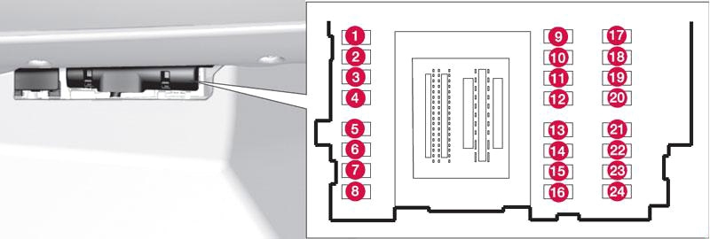
| № | Function | A |
|---|---|---|
| 1 | Rear window wiper | 15 |
| 2 | - | - |
| 3 | Interior lighting, Driver's door control panel, power windows, Power seats, front, Remote controlled garage door opener | 7.5 |
| 4 | Combined instrument panel | 5 |
| 5 | Adaptive cruise control, ACC; collision warning system | 10 |
| 6 | Interior lighting; Rain sensor | 7.5 |
| 7 | Steering wheel module | 7.5 |
| 8 | Central locking system, fuel filler flap | 10 |
| 9 | Heated steering wheel | 15 |
| 10 | 2014-2016: Heated windscreen | 15 |
| 11 | Unlocking, tailgate | 10 |
| 12 | 2013-2018: Folding head restraint | 10 |
| 13 | Fuel pump | 20 |
| 14 | Movement detector for alarm, Climate panel | 5 |
| 15 | Steering lock | 15 |
| 16 | Siren, Data link connector OBDII | 5 |
| 17 | - | - |
| 18 | Airbags | 10 |
| 19 | Collision warning system | 5 |
| 20 | Accelerator pedal sensor; Dimming interior rearview mirror; Seat heating, rear | 7.5 |
| 21 | Infotainment control module (Performance), Audio (Performance) | 15 |
| 22 | Brake light | 5 |
| 23 | Sunroof | 20 |
| 24 | Immobiliser | 5 |
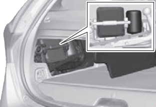
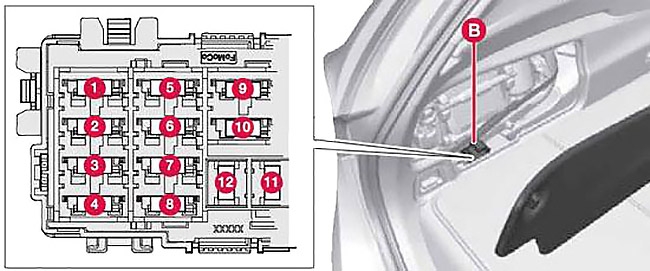
Luggage Compartment Fuse Box
The fuse box is located behind the upholstery on the left-hand side.
The emergency puncture repair kit needs to be lifted out for the central electrical unit to be accessible.
Box №1 Diagram
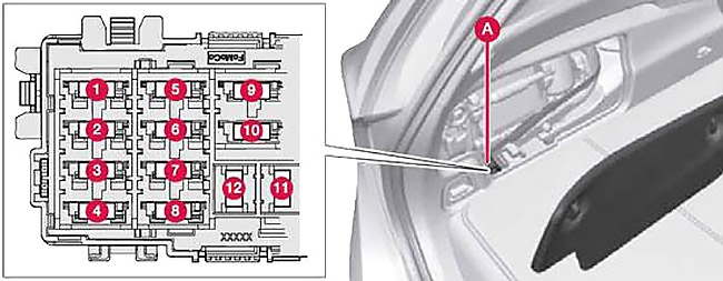
| № | Function | A |
|---|---|---|
| 1 | Electric parking brake, left | 30 |
| 2 | Electric parking brake, right | 30 |
| 3 | Rear window defroster | 30 |
| 4 | Trailer socket 2 | 15 |
| 5 | - | - |
| 6 | 12 V socket, cargo area | 15 |
| 7 | - | - |
| 8 | - | - |
| 9 | - | - |
| 10 | - | - |
| 11 | Trailer socket 1 | 40 |
| 12 | - | - |
Advertisements
Box №2 Diagram
| № | Function | A |
|---|---|---|
| 1 | Coolant pump 1 for hybrid battery | 10 |
| Valve for coolant pumps 1 and 2 | ||
| 2 | Coolant pump 2 for hybrid battery | 10 |
| 3 | Charging unit | 5 |
| Voltage converter 400 V-12 V | ||
| Control module for hybrid battery | ||
| 4 | Coolant pump for the cooling system's low temperature circuit | 15 |
| 5 | Charging unit | 10 |
| Voltage converter 400 V-12 V | ||
| Control module for hybrid battery | ||
| 6 | Relay coils; high voltage converter for electric motor and integrated starter generator | 10 |
| 7 | Disengaging the electric motor from the rear axle | 15 |
| 8 | - | - |
| 9 | High voltage converter for electric motor and integrated starter generator; control module for hybrid battery | 10 |
| 10 | Coolant valves for the cooling system's low temperature circuit | 10 |
| Electric A/C compressor | ||
| Valve for heat exchanger | ||
| Valve for climate control system | ||
| 11 | - | - |
| 12 | - | - |
Advertisements