
Advertisements
Fuse box diagram (fuse layout), location, and assignment of fuses and relays Volkswagen Touareg (7L facelift) (2005, 2006, 2007, 2008, 2009, 2010).

Checking and Replacing Fuses
The fuses are designed to blow before the entire wiring harness is damaged. If any of the electrical components do not operate, a fuse may have blown. If this happens, check and replace the fuses as necessary.
- Switch off the headlights, the ignition, and all electrical consumers.
- Open the appropriate fuse box.
- See diagrams below for details about which fuse to check.
- Remove the fuse using the plastic tweezers located on the fuse box cover.
- Check if the fuse is blown – if the thin metal strip inside is broken, the fuse has blown.
- If the fuse is blown, replace the fuse with a new fuse of the same amperage (same color and same imprint) and the same overall size.
- Replace the cover.
Notice
- Never replace a fuse with one that has a higher amp rating. Replace a blown fuse only with a fuse of the same amperage (same color and same imprint) and the same overall size.
- Never repair fuses.
- Never replace fuses with a metal strip, a paper clip, or a similar object.
- If a newly replaced fuse blows again after a short time, the electrical system should be checked by an authorized Volkswagen dealer or an authorized Volkswagen Service Facility.
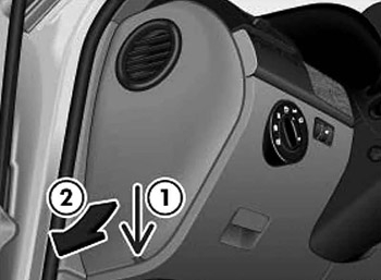
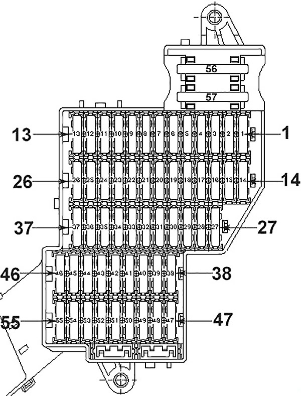
Left Instrument Panel Fuse Box
The fuse panel is located behind the cover on the left side end of the dashboard.
| № | А | Function/component |
|---|---|---|
| 1 | 15 | U1 - Cigarette lighter |
| 20 (*2, *8) | U9 - Rear cigarette lighter | |
| 2 | 5 (*8,*1,*7) | J160 - Circulation pump relay (*2) |
| 15 (*2,*7) | J708 - Residual heat relay (*2) | |
| R149 - Remote control receiver for auxiliary coolant heater (*2) | ||
| U18 - 12 V socket 2 (*1) | ||
| U20 - 12 V socket 4 (*1) | ||
| 3 | 15 | U5 - 12 V socket |
| 20 (*2) | U19 - 12 V socket 3 | |
| 4 | 20 | J162 - Heater control unit |
| 5 | 20 | U18 - 12 V socket 2 (*2) |
| U19 - 12 V socket 4 (*2) | ||
| J807 - Relay for power sockets (*1) | ||
| 6 | 15 | J518 - Entry and start authorisation control unit (*3) |
| J708 - Residual heat relay (*1) | ||
| 7 | 5 | T16b - Diagnostic connection |
| J515 - Aerial selection control unit | ||
| G397 - Rain and light detector sensor | ||
| 8 | 25 | V - Windscreen wiper motor |
| 30 (*7) | ||
| 9 | 15 | J519 - Onboard supply control unit (windscreen wiper pump) |
| 10 | 25 | J388 - Rear left door control unit (window regulator) |
| 30 (*7) | ||
| 11 | 15 | J386 - Driver door control unit (central locking) |
| J388 - Rear left door control unit (central locking) | ||
| 12 | 10 | J519 - Onboard supply control unit (interior light) |
| 13 | - | Not assigned |
| 14 | 25 | J386 - Driver door control unit (window regulator) |
| 30 (*7) | ||
| 15 | 15 | J393 - Convenience system central control unit (right tail light cluster) |
| 16 | 20 | J519 - Onboard supply control unit (fanfare) |
| 17 | 30 | J519 - Onboard supply control unit (left light) |
| 18 | 20 | J39 - Headlight washer system relay |
| 25 (*7) | ||
| 19 | - | Not assigned |
| 20 | 30 | J519 - Onboard supply control unit (battery 1) |
| 21 | - | Not assigned |
| 22 | 30 | J647 - Axle differential lock control unit |
| J605 - Rear lid control unit | ||
| 23 | 10 | J647 - Axle differential lock control unit |
| 24 | 5 | J502 - Tyre pressure monitor control unit |
| 25 | 15 | J352 - Steering column and belt height adjustment control unit |
| 26 | 10 | F36 - Clutch pedal switch |
| J... - Engine control units | ||
| J234 - Airbag control unit | ||
| J285 - Control unit in dash panel insert | ||
| J519 - Onboard supply control unit | ||
| K145 - Front passenger side airbag deactivated warning lamp | ||
| N378 - Driver seat belt inertia reel magnet | ||
| N379 - Front passenger side seat inertia reel magnet | ||
| 27 | 5 | E183 - Interior monitoring switch |
| W11 - Rear left reading light | ||
| W12 - Rear right reading light | ||
| W14 - Front passenger side illuminated vanity mirror | ||
| W20 - Driver side illuminated vanity mirror | ||
| W51 - Rear lid light | ||
| 28 | - | Not assigned |
| 29 | - | Not assigned |
| 30 | - | Not assigned |
| 31 | - | Not assigned |
| 32 | - | Not assigned |
| 33 | 15 | J527 - Steering column electronics control unit |
| 34 | 5 | G273 - Interior monitoring sensor |
| G384 - Vehicle inclination sender | ||
| J285 - Control unit in dash panel insert (*2) | ||
| 35 | 30 | J519 - Onboard supply control unit |
| 36 | 30 | E470 - Driver seat adjustment operating unit |
| 37 | - | Not assigned |
| 38 | - | Not assigned |
| 39 | 5 | J9 - Heated rear window relay |
| J32 - Air conditioning system relay | ||
| J329 - Terminal 15 voltage supply relay | ||
| J755 - Transport mode relay | ||
| J807 - Relay for power sockets (*1) | ||
| 40 | 5 | J285 - Control unit in dash panel insert |
| 41 | 15 | J518 - Entry and start authorisation control unit |
| 42 | 30 | J245 - Sliding sunroof adjustment control unit |
| 43 | - | Not assigned |
| 44 | 30 | E470 - Driver seat adjustment operating unit |
| J136 - Seat and steering column adjustment control unit with memory | ||
| J810 - Driver seat adjustment control unit | ||
| 45 | 25 | J786 - Heated rear seats control unit |
| 46 | - | Not assigned |
| 47 | 10 | J647 - Axle differential lock control unit |
| 48 | 5 | J769 - Lane change assist control unit |
| J770 - Lane change assist control unit 2 | ||
| 49 | 5 | J236 - Servotronic control unit |
| 50 | 10 | G266 - Oil level and oil temperature sender |
| N79 - Crankcase breather heater element (*4) | ||
| 51 | 5 | T16b - Diagnostic connection |
| F321 - Parking brake contact switch | ||
| G238 - Air quality sensor | ||
| G550 - Sensor for automatic distance control | ||
| J755 - Transport mode relay | ||
| 52 | 30 | V12 - Rear window wiper motor |
| 15 (*7) | ||
| 53 | 5 | E1 - Light switch |
| J527 - Steering column electronics control unit | ||
| J393 - Convenience system central control unit | ||
| 54 | 10 | E102 - Headlight range control regulator (*5) |
| J667 - Power output module for left headlight (*6) | ||
| V48 - Left headlight range control motor (*5) | ||
| V49 - Right headlight range control motor (*5) | ||
| 55 | 15 | J486 - Fresh air blower relay for 2nd speed |
| 56 | 40 | J32 - Air conditioning system relay |
| J309 - Solar cell isolation relay | ||
| J486 - Fresh air blower relay, 2nd speed | ||
| SB55 - Fuse 55 on fuse holder B | ||
| V305 - Motor for front Bitron blower regulation | ||
| 57 | 40 | V306 - Motor for rear Bitron blower regulation (*8) |
| J403 - Adaptive suspension compressor relay (*7) | ||
| 1) Only one battery onboard supply 2) Only auxiliary battery and two battery onboard supply 3) Only V10 TDI 4) Only models with engine codes BHK, BHL 5) Only models with halogen headlights 6) Only models with cornering light 7) From November 2007 8) Up to November 2007 | ||
Advertisements
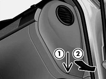
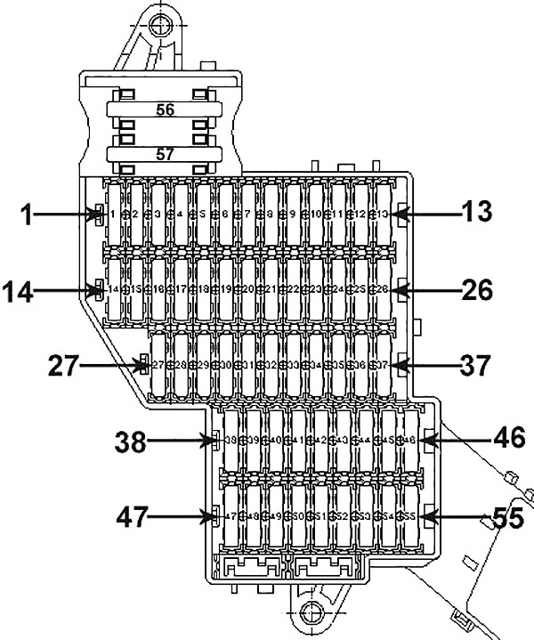
Right Instrument Panel Fuse Box
The fuse panel is located behind the cover on the right-side end of the dashboard.
| № | А | Function/component |
|---|---|---|
| 1 | 15 | J345 - Trailer detector control unit |
| 20 (*2) | ||
| 2 | 5 | J446 - Parking aid control unit |
| 3 | 15 | J345 - Trailer detector control unit |
| 4 | 5 | J412 - Mobile telephone operating electronics control unit |
| 5 | 15 | J345 - Trailer detector control unit |
| 25 (*2) | ||
| 6 | 30 | J104 - ABS control unit |
| 7 | 5 | J646 - Transfer box control unit |
| 8 | 30 | J519 - Onboard supply control unit (right light) |
| 9 | 10 | Individualisation |
| R190 - Satellite digital radio tuner (*1) | ||
| 10 | 5 | J772 - Reversing camera system control unit |
| R78 - TV tuner | ||
| 11 | 20 | J503 - Control unit with display for radio and navigation system |
| R - Radio | ||
| R - Preparation for radio and navigation system with TV (models for Japan) | ||
| 12 | 30 | R12 - Amplifier |
| 13 | - | Not assigned |
| 14 | 15 | J393 - Convenience system central control unit |
| 15 | 25 | J389 - Rear right door control unit (window regulator) |
| 30 (*3) | ||
| 16 | 10 | W3 - Luggage compartment light |
| 5 (*3) | ||
| 17 | - | Not assigned |
| 18 | 30 | J9 - Heated rear window relay |
| 19 | - | Not assigned |
| 20 | 30 | U13 - AC/DC converter with socket 12 V - 230 V |
| U27 - AC/DC converter with socket 12 V - 115 V (*1) | ||
| 21 | 10 | F266 - Bonnet contact switch |
| 22 | 25 | J774 - Heated front seats control unit |
| 23 | 10 | J255 - Climatronic control unit |
| 24 | 30 | E471 - Front passenger seat adjustment operating unit |
| J521 - Front passenger seat adjustment with memory control unit | ||
| 25 | 5 | E265 - Rear Climatronic operating and display unit |
| J301 - Air conditioning system control unit | ||
| 26 | - | Not assigned |
| 27 | 15 | J197 - Adaptive suspension control unit |
| 28 | - | Not assigned |
| 29 | 10 | J217 - Automatic gearbox control unit |
| 5 (*3) | ||
| 30 | 20 | J714 - Power latching system relay |
| 31 | 15 | J393 - Convenience system central control unit |
| 32 | 10 | J387 - Front passenger door control unit (central locking) |
| J389 - Rear right door control unit (central locking) | ||
| 33 | 15 | Individualisation |
| 34 | 25 | J387 - Front passenger side door control unit (window regulator) |
| 30 (*3) | ||
| 35 | 30 | E471 - Front passenger seat adjustment operating unit |
| 36 | 5 | J603 - Vehicle position recognition control unit |
| J702 - Roof display unit | ||
| 37 | - | Not assigned |
| 38 | 10 | J104 - ABS control unit |
| 39 | 5 | J410 - Heated windscreen relay for left side |
| J411 - Heated windscreen relay for right side | ||
| J745 - Cornering light and headlight range control unit | ||
| Individualisation | ||
| 40 | 10 | J646 - Transfer box control unit |
| 41 | 10 | J345 - Trailer detector control unit |
| 42 | 5 | E284 - Garage door operating unit |
| J530 - Garage door operation control unit | ||
| 43 | 5 | F41 - Reversing switch |
| 44 | 5 | E94 - Heated driver seat regulator |
| E95 - Heated front passenger seat regulator | ||
| E128 - Heated rear left seat switch with regulator | ||
| E129 - Heated rear right seat switch with regulator | ||
| E281 - Operating unit to regulate suspension height | ||
| Z20 - Left washer jet heater element | ||
| Z21 - Right washer jet heater element | ||
| 45 | - | Not assigned |
| 46 | - | Not assigned |
| 47 | 10 | J668 - Power output module for right headlight |
| 48 | 10 | J197 - Adaptive suspension control unit |
| 49 | 5 | Y7 - Automatic anti-dazzle interior mirror |
| 50 | 5 | E256 - TCS and ESP button |
| 51 | 15 | J217 - Automatic gearbox control unit |
| 52 | 5 | F125 - Multifunction switch |
| F189 - Tiptronic switch | ||
| N380 - Selector lever lock for position P solenoid | ||
| 53 | 30 | J411 - Heated windscreen relay for right side |
| 54 | 30 | J410 - Heated windscreen relay for left side |
| 55 | - | Not assigned |
| 56 | 40 | J104 - ABS control unit |
| 57 | 40 | J646 - Transfer box control unit |
| 1) Only American markets 2) From May 2008 3) From November 2007 | ||
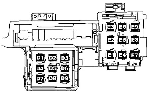
Relay Block
Left-hand drive
It is under the dashboard near the central console.
| № | Function/component |
|---|---|
| D1 | Servotronic control unit -J236- (476) |
| D2 | Power latching system relay -J714- (404) |
| D3 | Adaptive suspension compressor relay -J403- (373) |
| D4 | Power sockets relay -J807- (404) |
| D5 | Air conditioning system relay -J32- (100) / (370) optional installation |
| D6 | Fresh air blower relay, 2nd speed -J486- (404), only manually operated air conditioning system |
| D7 | Heated rear window relay -J9- (53) |
| D8 | Circulation pump relay -J160- (404), only VR6 with auxiliary heater |
| D9 | Alternator cut-in relay -J442- (53) |
| E1 | Solar cells isolation relay -J309- (79) |
| E2 | Not assigned |
| E3 | Heated windscreen relay for left side -J410- (53) |
| E4 | Not assigned |
| E5 | Voltage supply relay 2 -J710- (432), only V10 TDI |
| E6 | Not assigned |
| E7 | Headlight washer system relay -J39- (53) |
| E8 | Residual heat relay -J708- (404) |
| E9 | Heated windscreen relay for right side -J411- (53) |
Advertisements
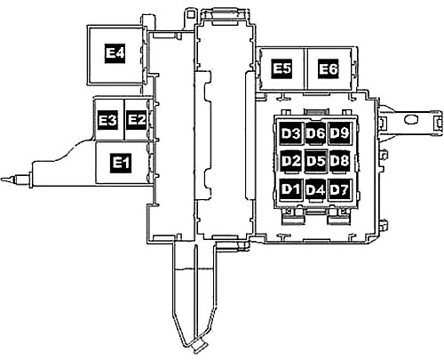
Right-hand drive
Located on the right under dash panel, near right a-pillar.
| № | Function/component |
|---|---|
| D1 | Servotronic control unit -J236- (476) |
| D2 | Power latching system relay -J714- (404) |
| D3 | Adaptive suspension compressor relay -J403- (373) |
| D4 | Power sockets relay -J807- (404) |
| D5 | Air conditioning system relay -J32- (100) / (370) optional installation |
| D6 | Fresh air blower relay, 2nd speed -J486- (404), only manually operated air conditioning system |
| D7 | Heated rear window relay -J9- (53) |
| D8 | Circulation pump relay -J160- (404), only VR6 with auxiliary heater |
| D9 | Alternator cut-in relay -J442- (53) |
| E1 | Solar cells isolation relay -J309- (79) |
| E2 | Residual heat relay -J708- (404) |
| E3 | Heated windscreen relay for left side -J410- (53) |
| E4 | Voltage supply relay 2 -J710- (432), only V10 TDI |
| E5 | Heated windscreen relay for right side -J411- (53) |
| E6 | Headlight washer system relay -J39- (53) |
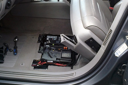
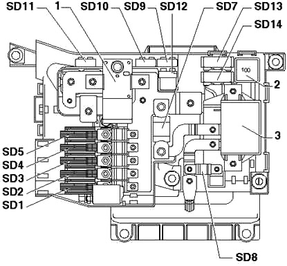
Pre-Fuse Box
Located on the battery under the driver seat.
| № | А | Function/component |
|---|---|---|
| SD1 | 150 | Left fuse carrier |
| SD2 | 150 | Right fuse carrier |
| SD3 | 60 | Right fuse carrier |
| SD4 | 60 | J701 - Voltage supply relay 2 (*1) |
| 40 (*3) | V306 - Motor for rear Bitron blower regulation (*3) | |
| SD5 | 60 | J329 - Terminal 15 voltage supply relay |
| 40 (*3) | ||
| SD6 | - | Not assigned |
| SD7 | 250 | J713 - Charger relay for second battery |
| SD8 | 150 (*1) | Left fuse carrier |
| 60 (*2) | J701 - Voltage supply relay 1 (*1) | |
| SD9 | 5 | J519 - Onboard supply control unit |
| SD10 | 10 | J519 - Onboard supply control unit (*1) |
| 5 (*3) | ||
| SD11 | 5 | J519 - Onboard supply control unit (*1) |
| SD12 | - | Not assigned |
| SD13 | 40 | J403 - Adaptive suspension compressor relay |
| #rowspan##rowspan# | V306 - Motor for rear Bitron blower regulation (*1,*3) | |
| SD14 | - | Not assigned |
| 1 | Battery master/isolator switch -E74- | |
| 2 | Terminal 15 voltage supply relay -J329- (433) | |
| 3 | Second battery charging circuit relay -J713- | |
| 1) Only V10 TDI 2) Only models with additional battery 3) From November 2007 | ||
Advertisements
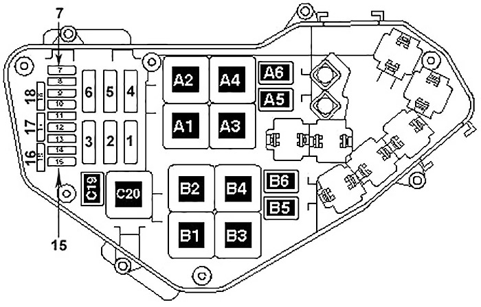
Engine Compartment Fuse Box
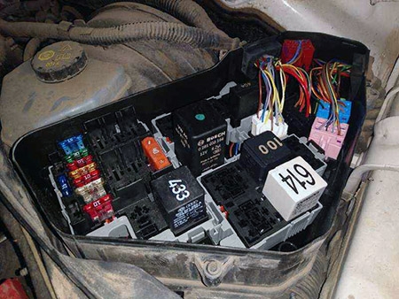
Diagram (2.5L (R5) TDI engine)
| № | A | Function/component |
|---|---|---|
| 1 | 60 | J293 - Radiator fan control unit |
| 2 | 30 | J671 - Radiator fan control unit 2 (*1) |
| 3 | - | Not assigned |
| 4 | - | Not assigned |
| 5 | - | Not assigned |
| 6 | - | Not assigned |
| 7 | - | Not assigned |
| 8 | - | Not assigned |
| 9 | 30 | J623 - Engine control unit |
| 10 | 10 | G65 - High-pressure sender |
| J17 - Fuel pump relay | ||
| J255 - Climatronic control unit | ||
| J293 - Radiator fan control unit | ||
| J301 - Air conditioning system control unit | ||
| J445 - Fuel cooling pump relay | ||
| J496 - Additional coolant pump relay | ||
| J671 - Radiator fan control unit 2 | ||
| N75 - Charge pressure control solenoid valve | ||
| N79 - Crankcase breather heater element | ||
| N280 - Air conditioner compressor regulating valve | ||
| N345 - Exhaust gas recirculation cooler changeover valve | ||
| 11 | - | Not assigned |
| 12 | 10 | J179 - Automatic glow period control unit |
| J496 - Additional coolant pump relay | ||
| 13 | 25 | G6 - Fuel system pressurisation pump |
| G23 - Fuel pump | ||
| J17 - Fuel pump relay | ||
| J445 - Fuel cooling pump relay | ||
| J715 - Tank circuit pressurisation relay | ||
| V166 - Fuel cooling pump | ||
| 14 | - | Not assigned |
| 15 | - | Not assigned |
| 16 | - | Not assigned |
| 17 | 10 | G39 - Lambda probe |
| Z19 - Lambda probe heater | ||
| 18 | - | Not assigned |
| A1 | Not assigned | |
| A2 | Terminal 30 voltage supply relay -J317- (109) | |
| A3 | Automatic glow period control unit -J179- (475) | |
| A4 | Fuel pump relay -J17- (53) | |
| A5 | Additional coolant pump relay -J496- (404) | |
| A6 | Fuel cooling pump relay -J445- (404) | |
| B1 | Not assigned | |
| B2 | Not assigned | |
| B3 | Not assigned | |
| B3 | Not assigned | |
| B4 | Not assigned | |
| B5 | Not assigned | |
| B6 | Not assigned | |
| C19 | Tank circuit pressurisation relay -J715- (404) (Only auxiliary coolant heater) | |
| C20 | Terminal 50 voltage supply relay -J682- (433) | |
| 1) Only models for tropical climate zones and models with towing coupling | ||
Diagram (3.0L (V6) diesel engine)
| № | A | Function/component |
|---|---|---|
| 1 | 60 | J293 - Radiator fan control unit |
| 30 (*1) | ||
| 2 | 30 | J671 - Radiator fan control unit 2 |
| 3 | - | Not assigned |
| 4 | 80 | J360 - High heat output relay (*3) |
| 5 | 40 | J359 - Low heat output relay (*3) |
| 6 | - | Not assigned |
| 7 | 15 | N276 - Fuel pressure regulating valve |
| N290 - Fuel metering valve | ||
| J17 - Fuel pump relay (*3) | ||
| 8 | - | Not assigned |
| 9 | 30 | J248 - Diesel direct injection system control unit |
| J623 - Engine control unit | ||
| 10 | 10 | G65 - High-pressure sender |
| J17 - Fuel pump relay | ||
| J179 - Automatic glow period control unit | ||
| J255 - Climatronic control unit | ||
| J293 - Radiator fan control unit | ||
| J301 - Air conditioning system control unit | ||
| J338 - Throttle valve module (*3) | ||
| J442 - Alternator cut-in relay (*2) | ||
| J445 - Fuel cooling pump relay | ||
| J496 - Additional coolant pump relay | ||
| J671 - Radiator fan control unit 2 | ||
| J724 - Turbocharger 1 control unit | ||
| J865 - Control unit for charge air cooler bypass (*3) | ||
| N18 - Exhaust gas recirculation valve | ||
| N280 - Air conditioner compressor regulating valve | ||
| N345 - Exhaust gas recirculation cooler changeover valve | ||
| N381 - Exhaust gas recirculation cooler changeover valve 2 (*3) | ||
| N428 - Valve block 2 in front passenger side rear seat (*3) | ||
| V157 - Intake manifold flap motor | ||
| V275 - Intake manifold flap 2 motor | ||
| V400 - Pump for exhaust gas recirculation cooler (*3) | ||
| 11 | 15 | J445 - Fuel cooling pump relay (*3) |
| J832 - Relay for supplementary fuel pump (*3) | ||
| V166 - Fuel cooling pump (*3) | ||
| V393 - Supplementary fuel pump (*3) | ||
| 12 | 10 | J496 - Additional coolant pump relay |
| 13 | 25 | G6 - Fuel system pressurisation pump |
| 20 (*3) | G23 - Fuel pump | |
| J17 - Fuel pump relay (*3) | ||
| J445 - Fuel cooling pump relay | ||
| J715 - Tank circuit pressurisation relay | ||
| V166 - Fuel cooling pump | ||
| 14 | 15 | G698 - Evaluation unit for reducing agent level (*3) |
| N473 - Reversing valve for reducing agent (*3) | ||
| V437 - Reducing agent pump (*3) | ||
| Z103 - Heater for reducing agent pump (*3) | ||
| 15 | 10 | J317 - Terminal 30 voltage supply relay |
| J623 - Engine control unit (*3) | ||
| 16 | 30 | J891 - Control unit for reducing agent heater |
| 17 | 20 | J583 - NOx sensor control unit (*3) |
| 15 (*1) | J881 - NOx sensor 2 control unit (*3) | |
| G39 - Lambda probe | ||
| Z19 - Lambda probe heater | ||
| 18 | - | Not assigned |
| A1 | Not assigned | |
| A2 | Terminal 30 voltage supply relay -J317- (219) / (643) optional installation | |
| A3 | Automatic glow period control unit -J179- (475) / (639) / (647) optional installlation | |
| A4 | Not assigned | |
| A5 | Additional coolant pump relay -J496- (404 / (449) optional installation | |
| A6 | Fuel cooling pump relay -J445- (404) / (449) optional installation | |
| B1 | Not assigned | |
| B2 | Fuel pump relay -J17- (53) | |
| B3 | Not assigned | |
| B3 | High heat output relay -J360- (100) | |
| B4 | Low heat output relay -J359- (100) | |
| B5 | Not assigned | |
| B6 | Not assigned | |
| C19 | Tank circuit pressurisation relay -J715- (404) (Only auxiliary coolant heater) | |
| C20 | Terminal 50 voltage supply relay -J682- (433) | |
| 1) Depends on equipment 2) Up to May 2007 3) Only models with engine code CATA | ||
Advertisements
Diagram (5.0L (V10) TDI engine)
| № | A | Function/component |
|---|---|---|
| 1 | 60 | J293 - Radiator fan control unit |
| 2 | 60 (*1) | J671 - Radiator fan control unit 2 |
| 30 | V177 - Radiator fan 2 | |
| 3 | - | Not assigned |
| 4 | - | Not assigned |
| 5 | - | Not assigned |
| 6 | 60 | J701 - Voltage supply relay 1 |
| 7 | 10 | J708 - Residual heat relay |
| J496 - Additional coolant pump relay | ||
| J445 - Fuel cooling pump relay | ||
| V166 - Fuel cooling pump | ||
| 8 | 30 | J624 - Engine control unit 2 |
| 9 | 30 | J623 - Engine control unit |
| 10 | 10 | G65 - High-pressure sender |
| J17 - Fuel pump relay | ||
| J293 - Radiator fan control unit | ||
| J671 - Radiator fan control unit 2 | ||
| N345 - Exhaust gas recirculation cooler changeover valve | ||
| N381 - Exhaust gas recirculation cooler changeover valve 2 | ||
| V336 - Metering pump for post-injection in particulate filter for cylinder bank 1 (*2) | ||
| V337 - Metering pump for post-injection in particulate filter for cylinder bank 2 (*2) | ||
| 11 | 15 | F265 - Map-controlled engine cooling system thermostat |
| J255 - Climatronic control unit | ||
| J724 - Turbocharger 1 control unit | ||
| J725 - Turbocharger 2 control unit | ||
| N280 - Air conditioner compressor regulating valve | ||
| V135 - Particulate filter additive pump (*2) | ||
| V157 - Intake manifold flap motor | ||
| V275 - Intake manifold flap 2 motor | ||
| V280 - Turbocharger 1 control motor | ||
| V281 - Turbocharger 2 control motor | ||
| 12 | 5 | J179 - Automatic glow period control unit |
| J445 - Fuel cooling pump relay | ||
| J496 - Additional coolant pump relay | ||
| J703 - Glow period control unit 2 | ||
| 13 | 25 (*3) | G6 - Fuel system pressurisation pump |
| 30 | G23 - Fuel pump | |
| J17 - Fuel pump relay | ||
| J715 - Tank circuit pressurisation relay (*3) | ||
| 14 | - | Not assigned |
| 15 | 10 | J317 - Terminal 30 voltage supply relay |
| 16 | 10 | J581 - Battery parallel circuit relay |
| 17 | 20 | G39 - Lambda probe |
| G108 - Lambda probe 2 | ||
| Z19 - Lambda probe heater | ||
| Z28 - Lambda probe heater 2 | ||
| 18 | - | Not assigned |
| A1 | Glow period control unit 2 -J703- (475) | |
| A2 | Terminal 30 voltage supply relay 2 -J689- (219) | |
| A3 | Automatic glow period control unit -J179- (475) | |
| A4 | Not assigned | |
| A5 | Additional coolant pump relay -J496- (404) | |
| A6 | Fuel cooling pump relay -J445- (404) | |
| B1 | Terminal 30 voltage supply relay -J317- (219) | |
| B2 | Fuel pump relay -J17- (53) | |
| B3 | Not assigned | |
| B3 | Not assigned | |
| B4 | Voltage supply relay 1 -J701- (100) / (370) optional installation | |
| B5 | Not assigned | |
| B6 | Not assigned | |
| C19 | Tank circuit pressurisation relay -J715- (404) (Not for American markets) | |
| C20 | Terminal 50 voltage supply relay -J682- (433) | |
| 1) Only models for tropical climate zones and models with towing coupling 2) Only American markets 3) Not American markets | ||
Diagram (3.2L (V6) petrol engine)
| № | A | Function/component |
|---|---|---|
| 1 | 60 | J293 - Radiator fan control unit |
| 2 | 30 | J671 - Radiator fan control unit 2 |
| 3 | 40 | V101 - Secondary air pump motor |
| 4 | - | Not assigned |
| 5 | - | Not assigned |
| 6 | - | Not assigned |
| 7 | 20 | N30 - Injector, cylinder 1 |
| N31 - Injector, cylinder 2 | ||
| N32 - Injector, cylinder 3 | ||
| N70 - Ignition coil 1 with power output stage | ||
| N127 - Ignition coil 2 with power output stage | ||
| N291 - Ignition coil 3 with power output stage | ||
| 8 | 20 | N33 - Injector, cylinder 4 |
| N83 - Injector, cylinder 5 | ||
| N84 - Injector, cylinder 6 | ||
| N292 - Ignition coil 4 with power output stage | ||
| N323 - Ignition coil 5 with power output stage | ||
| N324 - Ignition coil 6 with power output stage | ||
| 9 | 30 | J220 - Motronic control unit |
| N156 - Variable intake manifold changeover valve | ||
| N205 - Inlet camshaft control valve 1 | ||
| N318 - Exhaust camshaft control valve 1 | ||
| 10 | 10 | G65 - High-pressure sender |
| J293 - Radiator fan control unit | ||
| J569 - Brake servo relay | ||
| J671 - Radiator fan control unit 2 | ||
| N80 - Activated charcoal filter solenoid valve 1 | ||
| N115 - Activated charcoal filter solenoid valve 2 | ||
| V144 - Fuel system diagnostic pump | ||
| 11 | 15 | G266 - Oil level and oil temperature sender |
| J255 - Climatronic control unit | ||
| N280 - Air conditioner compressor regulating valve | ||
| 12 | 5 | J299 - Secondary air pump relay |
| J496 - Additional coolant pump relay | ||
| 13 | 15 | G23 - Fuel pump |
| 14 | 15 | G6 - Fuel system pressurisation pump |
| 15 | 10 | J17 - Fuel pump relay |
| J49 - Electric fuel pump 2 relay | ||
| J220 - Motronic control unit | ||
| J271 - Motronic current supply relay | ||
| J670 - Motronic current supply relay 2 | ||
| 16 | 15 | V192 - Vacuum pump for brakes |
| 17 | 15 | G39 - Lambda probe |
| G108 - Lambda probe 2 | ||
| 18 | 7.5 | G130 - Lambda probe after catalytic converter |
| G131 - Lambda probe 2 after catalytic converter | ||
| A1 | Terminal 30 voltage supply relay 2 -J689- (53) | |
| A2 | Not assigned | |
| A3 | Terminal 30 voltage supply relay -J317- (167 | |
| A4 | Secondary air pump relay -J299- (100) / (370) optional installation | |
| A5 | Additional coolant pump relay -J496- (404) | |
| A6 | Fuel pump relay -J17- (53) | |
| B1 | Not assigned | |
| B2 | Not assigned | |
| B3 | Not assigned | |
| B3 | Not assigned | |
| B4 | Not assigned | |
| B5 | Not assigned | |
| B6 | Brake servo relay -J569- (404) (Only models with automatic gearbox) | |
| C19 | Electric fuel pump 2 relay -J49- (404) | |
| C20 | Terminal 50 voltage supply relay -J682- (433) | |
Advertisements
Diagram (3.6L (V6) FSI engine)
| № | A | Function/component |
|---|---|---|
| 1 | 60 | J293 - Radiator fan control unit |
| 2 | 30 (*1) | J671 - Radiator fan control unit 2 |
| V7 - Radiator fan | ||
| 3 | - | Not assigned |
| 4 | - | Not assigned |
| 5 | - | Not assigned |
| 6 | - | Not assigned |
| 7 | 20 | N70 - Ignition coil 1 with output stage |
| N127 - Ignition coil 2 with output stage | ||
| N291 - Ignition coil 3 with output stage | ||
| 8 | 20 | N292 - Ignition coil 4 with output stage |
| N323 - Ignition coil 5 with output stage | ||
| N324 - Ignition coil 6 with output stage | ||
| 9 | 30 | J623 - Engine control unit |
| 10 | 10 | G65 - High-pressure sender |
| J293 - Radiator fan control unit | ||
| J496 - Additional coolant pump relay | ||
| J671 - Radiator fan control unit 2 (*1) | ||
| V144 - Fuel system diagnostic pump | ||
| 11 | 10 | J255 - Climatronic control unit |
| J301 - Air conditioning system control unit | ||
| J442 - Alternator cut-in relay (*2) | ||
| N280 - Air conditioner compressor regulating valve | ||
| 12 | 10 | N80 - Activated charcoal filter system solenoid valve 1 |
| N205 - Inlet camshaft control valve 1 | ||
| N316 - Intake manifold flap valve | ||
| N318 - Exhaust camshaft control valve 1 | ||
| 13 | 25 | J538 - Fuel pump control unit |
| 14 | 15 | N276 - Fuel pressure regulating valve |
| 15 | 10 | J623 - Engine control unit |
| J271 - Motronic current supply relay | ||
| J670 - Motronic current supply relay 2 | ||
| 16 | 15 | J496 - Additional coolant pump relay |
| 17 | 15 | G39 - Lambda probe |
| G108 - Lambda probe 2 | ||
| Z19 - Lambda probe heater | ||
| Z28 - Lambda probe heater 2 | ||
| 18 | 7.5 | G130 - Lambda probe after catalytic converter |
| G131 - Lambda probe 2 after catalytic converter | ||
| Z29 - Lambda probe 1 heater after catalytic converter | ||
| Z30 - Lambda probe 2 heater after catalytic converter | ||
| A1 | Not assigned | |
| A2 | Not assigned | |
| A3 | Motronic current supply relay -J271- (614) | |
| A4 | Not assigned | |
| A5 | Additional coolant pump relay -J496- (404) | |
| A6 | Not assigned | |
| B1 | Not assigned | |
| B2 | Not assigned | |
| B3 | Not assigned | |
| B3 | Not assigned | |
| B4 | Motronic current supply relay 2 -J670- (614) to May 2007 | |
| B5 | Not assigned | |
| B6 | Not assigned | |
| C19 | Not assigned | |
| C20 | Terminal 50 voltage supply relay -J682- (433) | |
| 1) Only models for tropical climate zones and models with towing coupling 2) Up to May 2007 | ||
Diagram (4.2L (V8) FSI engine)
| № | A | Function/component |
|---|---|---|
| 1 | 60 | J671 - Radiator fan control unit 2 |
| V177 - Radiator fan 2 | ||
| 2 | 60 (*1) | J293 - Radiator fan control unit |
| 30 | V7 - Radiator fan | |
| 3 | 40 | J299 - Secondary air pump relay |
| V101 - Secondary air pump motor | ||
| 4 | - | Not assigned |
| 5 | - | Not assigned |
| 6 | - | Not assigned |
| 7 | 20 | N70 - Ignition coil 1 with output stage |
| N127 - Ignition coil 2 with output stage | ||
| N291 - Ignition coil 3 with output stage | ||
| N292 - Ignition coil 4 with output stage | ||
| N323 - Ignition coil 5 with output stage | ||
| N324 - Ignition coil 6 with output stage | ||
| N325 - Ignition coil 7 with output stage | ||
| N326 - Ignition coil 8 with output stage | ||
| 8 | - | Not assigned |
| 9 | 30 | J623 - Engine control unit |
| 10 | 10 | G70 - Air mass meter |
| G246 - Air mass meter 2 | ||
| J299 - Secondary air pump relay | ||
| N80 - Activated charcoal filter solenoid valve 1 | ||
| V144 - Fuel system diagnostic pump | ||
| 11 | - | Not assigned |
| 12 | 20 | F265 - Map-controlled engine cooling system thermostat |
| G65 - High-pressure sender | ||
| J151 - Continued coolant circulation relay | ||
| J255 - Climatronic control unit | ||
| J301 - Air conditioning system control unit | ||
| J293 - Radiator fan control unit | ||
| J442 - Alternator cut-in relay (*2) | ||
| J671 - Radiator fan control unit 2 | ||
| N205 - Inlet camshaft control valve 1 | ||
| N208 - Inlet camshaft control valve 2 | ||
| N280 - Air conditioner compressor regulating valve | ||
| N318 - Exhaust camshaft control valve 1 | ||
| N319 - Exhaust camshaft control valve 2 | ||
| V157 - Intake manifold flap motor | ||
| V183 - Variable intake manifold motor | ||
| 13 | 25 | J538 - Fuel pump control unit |
| 14 | 10 | N290 - Fuel metering valve |
| N402 - Fuel metering valve 2 | ||
| 15 | 10 | J271 - Motronic current supply relay |
| J623 - Engine control unit | ||
| 16 | 15 | J569 - Brake servo relay |
| V192 - Vacuum pump for brakes | ||
| 17 | 10 | G39 - Lambda probe |
| G108 - Lambda probe 2 | ||
| 18 | 10 | G130 - Lambda probe after catalytic converter |
| G131 - Lambda probe 2 after catalytic converter | ||
| A1 | Not assigned | |
| A2 | Not assigned | |
| A3 | Automatic glow period control unit -J179- (475) | |
| A4 | Secondary air pump relay -J299- (100) / (370) optional installation | |
| A5 | Continued coolant circulation relay -J151- (404) | |
| A6 | Not assigned | |
| B1 | Not assigned | |
| B2 | Not assigned | |
| B3 | Not assigned | |
| B3 | Not assigned | |
| B4 | Engine components current supply relay -J757- (614) | |
| B5 | Not assigned | |
| B6 | Brake servo relay -J569- (404) (Only models with automatic gearbox) | |
| C19 | Not assigned | |
| C20 | Terminal 50 voltage supply relay -J682- (433) | |
| 1) Only models with towing coupling 2) Up to May 2007 | ||
Diagram (6.0 l (W12) petrol engine)
| № | A | Function/component |
|---|---|---|
| 1 | 60 | J671 - Radiator fan control unit 2 |
| V177 - Radiator fan 2 | ||
| 2 | 60 (*1) | J293 - Radiator fan control unit |
| 30 | V7 - Radiator fan | |
| 3 | 40 | J299 - Secondary air pump relay |
| V101 - Secondary air pump motor | ||
| 4 | 40 | J545 - Secondary air pump relay 2 |
| V189 - Secondary air pump motor 2 | ||
| 5 | 30 | N325 - Ignition coil 7 with output stage |
| N326 - Ignition coil 8 with output stage | ||
| N327 - Ignition coil 9 with output stage | ||
| N328 - Ignition coil 10 with output stage | ||
| N329 - Ignition coil 11 with output stage | ||
| N330 - Ignition coil 12 with output stage | ||
| S7 - Fuse in relay plate fuse holder | ||
| 6 | 30 | N70 - Ignition coil 1 with output stage |
| N127 - Ignition coil 2 with output stage | ||
| N291 - Ignition coil 3 with output stage | ||
| N292 - Ignition coil 4 with output stage | ||
| N323 - Ignition coil 5 with output stage | ||
| N324 - Ignition coil 6 with output stage | ||
| S8 - Fuse in relay plate fuse holder | ||
| 7 | 10 | N85 - Injector, cylinder 7 |
| N86 - Injector, cylinder 8 | ||
| N299 - Injector, cylinder 9 | ||
| N300 - Injector, cylinder 10 | ||
| N301 - Injector, cylinder 11 | ||
| N302 - Injector, cylinder 12 | ||
| 8 | 10 | N30 - Injector, cylinder 1 |
| N31 - Injector, cylinder 2 | ||
| N32 - Injector, cylinder 3 | ||
| N33 - Injector, cylinder 4 | ||
| N83 - Injector, cylinder 5 | ||
| N84 - Injector, cylinder 6 | ||
| 9 | 30 | J623 - Engine control unit |
| J624 - Engine control unit 2 | ||
| 10 | 10 | G65 - High-pressure sender |
| J255 - Climatronic control unit | ||
| J293 - Radiator fan control unit | ||
| J301 - Air conditioning system control unit | ||
| J442 - Alternator cut-in relay (*2) | ||
| J671 - Radiator fan control unit 2 | ||
| V144 - Fuel system diagnostic pump | ||
| 11 | 15 | N80 - Activated charcoal filter solenoid valve 1 |
| N205 - Inlet camshaft control valve 1 | ||
| N208 - Inlet camshaft control valve 2 | ||
| N280 - Air conditioner compressor regulating valve | ||
| N318 - Exhaust camshaft control valve 1 | ||
| N319 - Exhaust camshaft control valve 2 | ||
| 12 | 5 | J49 - Electric fuel pump 2 relay |
| J299 - Secondary air pump relay | ||
| J545 - Secondary air pump relay 2 | ||
| J624 - Engine control unit 2 | ||
| 13 | 15 | G6 - Fuel system pressurisation pump |
| J17 - Fuel pump relay | ||
| 14 | 15 | G23 - Fuel pump |
| J49 - Electric fuel pump 2 relay | ||
| 15 | 10 | J17 - Fuel pump relay |
| J271 - Motronic current supply relay | ||
| J623 - Engine control unit | ||
| J624 - Engine control unit 2 | ||
| 16 | 15 | J496 - Additional coolant pump relay |
| J569 - Brake servo relay | ||
| V51 - Continued coolant circulation pump | ||
| V192 - Vacuum pump for brakes | ||
| 17 | 30 | G39 - Lambda probe |
| G108 - Lambda probe 2 | ||
| G285 - Lambda probe 3 | ||
| G286 - Lambda probe 4 | ||
| Z19 - Lambda probe heater | ||
| Z28 - Lambda probe heater 2 | ||
| Z62 - Lambda probe heater 3 | ||
| Z63 - Lambda probe heater 4 | ||
| 18 | 15 | G130 - Lambda probe after catalytic converter |
| G131 - Lambda probe 2 after catalytic converter | ||
| G287 - Lambda probe 3 after catalytic converter | ||
| G288 - Lambda probe 4 after catalytic converter | ||
| Z29 - Lambda probe 1 heater after catalytic converter | ||
| Z30 - Lambda probe 2 heater after catalytic converter | ||
| Z64 - Lambda probe 3 heater after catalytic converter | ||
| Z65 - Lambda probe 4 heater after catalytic converter | ||
| A1 | Not assigned | |
| A2 | Not assigned | |
| A3 | Motronic current supply relay -J271- (100) / (370) optional installation | |
| A4 | Secondary air pump relay -J299- (100) / (370) optional installation | |
| A5 | Additional coolant pump relay -J496- (404) | |
| A6 | Electric fuel pump 2 relay -J49- (404) | |
| B1 | Not assigned | |
| B2 | Not assigned | |
| B3 | Not assigned | |
| B3 | Secondary air pump relay 2 -J545- (100) / (370) optional installation | |
| B4 | Not assigned | |
| B5 | Not assigned | |
| B6 | Brake servo relay -J569- (404) (Only models with automatic gearbox) | |
| C19 | Fuel pump relay -J17- (404) | |
| C20 | Terminal 50 voltage supply relay -J682- (433) | |
| 1) Only models with towing coupling 2) Up to May 2007 | ||
Advertisements