
Advertisements
Fuse box diagram (fuse layout), location, and assignment of fuses and relays Volkswagen Tiguan (5N) (2007, 2008, 2009, 2010, 2011, 2012).
Checking and Replacing Fuses
The fuses are designed to blow before the entire wiring harness is damaged. If any of the electrical components do not operate, a fuse may have blown. If this happens, check and replace the fuses as necessary.
- Switch off the headlights, the ignition, and all electrical consumers.
- Open the appropriate fuse box.
- See diagrams below for details about which fuse to check.
- Remove the fuse using the plastic tweezers located on the fuse box cover.
- Check if the fuse is blown – if the thin metal strip inside is broken, the fuse has blown.
- If the fuse is blown, replace the fuse with a new fuse of the same amperage (same color and same imprint) and the same overall size.
- Replace the cover.
Notice
- Never replace a fuse with one that has a higher amp rating. Replace a blown fuse only with a fuse of the same amperage (same color and same imprint) and the same overall size.
- Never repair fuses.
- Never replace fuses with a metal strip, a paper clip, or a similar object.
- If a newly replaced fuse blows again after a short time, the electrical system should be checked by an authorized Volkswagen dealer or an authorized Volkswagen Service Facility.
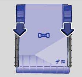
Engine Compartment Fuse Box
Move the release tabs in the direction of the arrows to unlock the fuse box cover. Remove the cover upward. To install – push the cover onto the fuse box and move release buttons back opposite the direction of the arrows, until they audibly latch.
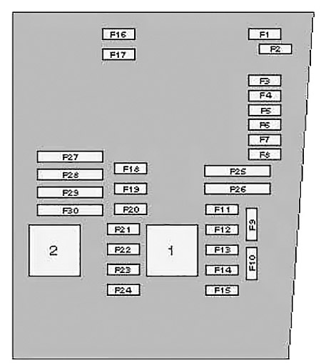
| № | A | Circuits protected |
|---|---|---|
| 1 | - | |
| 2 | - | |
| 3 | 5 | Multifunction control module 2 |
| 4 | 30 | ABS/ESP system |
| 5 | - | |
| 6 | 5 | Instrumentation control module, steering column function control module 2 |
| 7 | 40 | Ignition main circuits |
| 8 | 25 | In-car entertainment (ICE) |
| 8 | 25 | Voltage converter |
| 9 | 5 | Mobile telephone control module |
| 10 | 5 10 | Engine control module (ECM) |
| 11 | 20 | Auxiliary heater control module |
| 12 | 5 | CAN data bus gateway control module |
| 13 | 15 30 | Engine control module (ECM) |
| 14 | 5 | Engine management system |
| 15 | 5 10 15 | Fuel pump (FP), AC compressor clutch, engine management system |
| 16 | 30 | Multifunction control module 2 |
| 17 | 15 | Alarm system horn |
| 18 | 30 | Audio system |
| 19 | 30 | Windscreen wiper motor |
| 20 | 10 | Engine management system |
| 21 | 10 20 | Engine management system, fuel pump (FP) control module |
| 22 | 5 | Clutch pedal position (CPP) switch |
| 23 | 10 | Engine management system |
| 24 | 10 | Engine coolant blower motor control module, engine management system, engine coolant heater |
| 25 | 40 | ABS/ESP system |
| 26 | 30 | Multifunction control module 2 |
| 27 | - | |
| 28 | 50 | Glow plug control module |
| 29 | 50 | Electric seats |
| 30 | 50 | Ignition switch circuits |
| 1 | Engine control (EC) relay 1 (Petrol) Ignition main circuits relay (Diesel) | |
| 2 | Engine control (EC) relay 2 (Petrol) Engine control (EC) relay (Diesel) | |
Advertisements
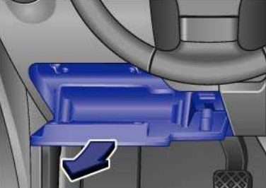
Passenger Compartment Fuse Box
The fuse panel is located behind the storage box on the driver’s side of the dashboard. Open the storage compartment and pull back firmly in the direction of the arrow.

| № | A | Circuits protected |
|---|---|---|
| 1 | - | |
| 2 | - | |
| 3 | - | |
| 4 | - | |
| 5 | - | |
| 6 | - | |
| 7 | - | |
| 8 | - | |
| 9 | 5 | Supplementary restraint system (SRS) control module |
| 10 | 10 | Four wheel drive control module |
| 11 | 5 | Parking aid control module, self-parking system control module |
| 12 | 10 | Gas discharge headlamp control module (LH) |
| 13 | 5 | ABS/ESP system, AC system, anti-dazzle interior mirror, heated windscreen washer jets, seat occupation control module, transmission control module (TCM), reversing lamps, engine management system |
| 14 | 10 | ABS control module, engine control module (ECM), heated seats, power steering control module, suspension control module, trailer control module, AC control module, instrumentation control module, CAN data bus gateway control module |
| 15 | 10 | Auxiliary heater, data link connector (DLC), parking brake control module, engine management, headlamp direction control module |
| 16 | 10 | Gas discharge headlamp control module (RH) |
| 17 | 5 | Instrument panel |
| 18 | 10 | Mobile telephone control module, multimedia control module |
| 19 | 10 | Steering column function control module 2 |
| 20 | 5 | ABS control module, AC system, transmission control module (TCM) |
| 21 | 15 | Door function control module, left rear, door function control module, right rear, multifunction control module 2 |
| 22 | 5 | Alarm system, multifunction control module 2 |
| 23 | 10 | ABS/ESP system, AC system, data link connector (DLC), rear view camera control module, headlamp switch |
| 24 | 10 | Door function control module, driver, door function control module, passenger |
| 25 | 20 | Transmission control module (TCM) |
| 26 | - | |
| 27 | - | |
| 28 | 40 | AC control module, auxiliary heater |
| 29 | 15 | Rear screen wiper motor |
| 30 | - | |
| 31 | 20 | Auxiliary power sockets, cigarette lighter |
| 32 | - | |
| 33 | - | |
| 34 | - | |
| 35 | - | |
| 36 | - | |
| 37 | - | |
| 38 | 10 | Steering column function control module 1 |
| 39 | 20 | Headlamp washers |
| 40 | 15 | Trailer control module |
| 41 | 15 | Trailer control module |
| 42 | 20 | Trailer control module |
| 43 | 25 | Sunroof control module |
| 44 | 25 | Parking brake control module |
| 45 | 25 | Heater blower motor, heated rear window |
| 46 | 30 | Door function control module, driver, door function control module, passenger |
| 47 | 30 | Door function control module, driver, door function control module, right rear |
| 48 | 15 | Fuel pump (FP) |
| 49 | 20 | Multifunction control module 2 |
| 50 | 25 | Parking brake control module |
| 51 | 40 | AC/heater blower motor control module |
| 52 | 30 | Seat heater control module |
| 53 | 20 30 | Headlamp washers |
| 54 | 30 | Auxiliary power sockets |
| 55 | 15 | Lumbar support adjustment |
| 56 | 15 | Suspension control module |
| 57 | 25 | Sun blind control module |
| 58 | 1 | Trailer warning lamp |
| 59 | 20 | Multimedia control module |
| 60 | - |
Relays are placed above the fuse box.
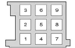
| № | Description |
|---|---|
| 1 | Auxiliary heater relay |
| 2 | Starter motor relay |
| 3 | - |
| 4 | Heater blower relay |
| 5 | Alarm system horn relay / headlamp washer pump relay |
| 6 | Fuel pump (FP) relay |
| 7 | Engine coolant heater relay 1 |
| 8 | Engine coolant pump relay - some models |
| Fuel pump (FP) relay - some models | |
| Auxiliary heater fuel pump relay - some models | |
| 9 | Engine coolant heater relay 2 |
Advertisements