
Advertisements
Fuse box diagram (fuse layout), location, and assignment of fuses and relays Toyota Yaris / Echo (XP10) (1999, 2000, 2001, 2002, 2003, 2004, 2005).
Checking and Replacing Fuses
The fuses are designed to blow before the entire wiring harness is damaged. If any of the electrical components do not operate, a fuse may have blown. If this happens, check and replace the fuses as necessary.
- Turn the engine switch off and turn off all electrical accessories.
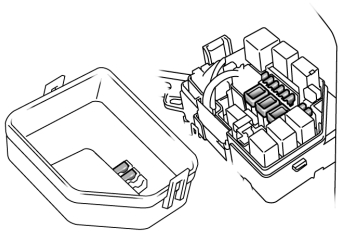
- Open the fuse box cover.
- See diagrams below for details about which fuse to check.
- Remove the fuse.
- Check if the fuse is blown – if the thin wire inside is broken, the fuse has blown.
- Replace the blown fuse with a new fuse of an appropriate amperage rating.
Notice
- Never use a fuse of a higher amperage rating than that indicated, or use any other object in place of a fuse, even as a temporary fix. This can cause extensive damage or even fire.
- Always use a genuine Toyota fuse or equivalent.
- Do not modify the fuses or fuse boxes.
- If the replaced fuse blows again, have the vehicle inspected by any authorized Toyota dealer or repairer, or another duly qualified and equipped professional.
Passenger Compartment
Left-hand drive
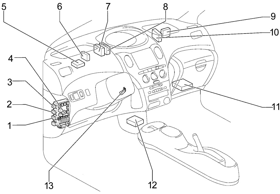
- Front Fog Light Relay
- Defogger Relay
- Taillight Relay
- Fuse Box
- Wireless Door Lock Control Receiver
- Active Light Relay
- Daytime Running Light Relay
- Door Lock Control Relay
- A/C Amplifier
- PTC Amplifier
- Engine and ECT ECU (A/T) or Engine ECU (M/T)
- Center Airbag Sensor Assembly
- Transponder Key Amplifier
Right-hand drive
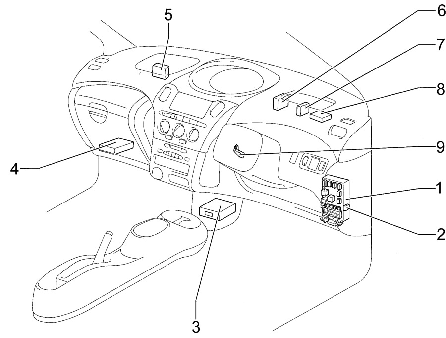
- Fuse Box
- Front Fog Light Relay
- Center Airbag Sensor Assembly
- Engine and ECT ECU (A/T) or Engine ECU (M/T)
- A/C Amplifier
- Door Lock Control Relay
- Active Light Relay
- Wireless Door Lock Control Receiver
- Transponder Key Amplifier
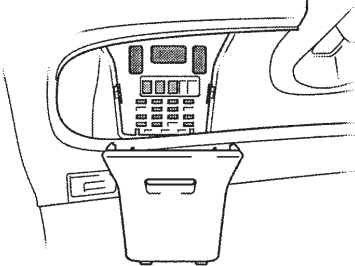
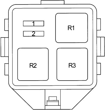
Passenger Compartment Fuse Box Diagram
The fuse panel is located behind the cover on the driver’s side of the dashboard.
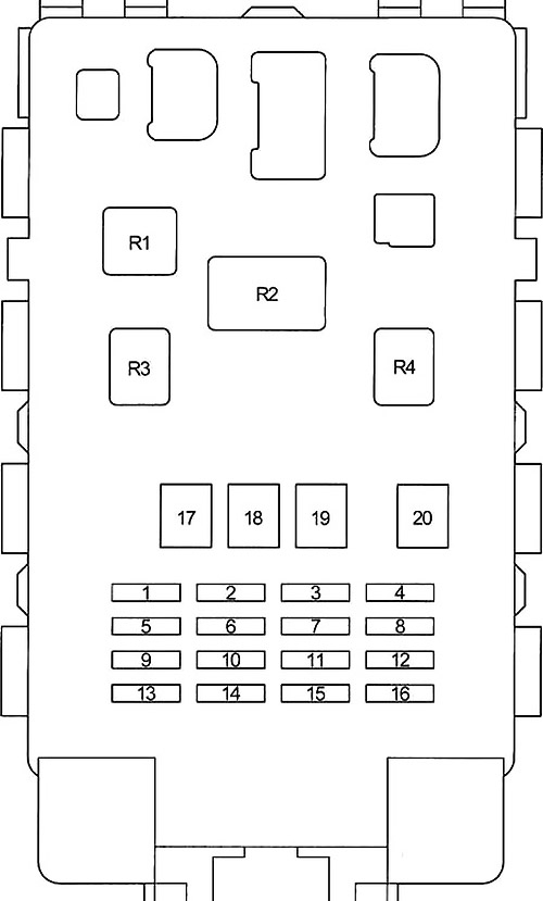
| № | Fuse | A | Circuit |
|---|---|---|---|
| 1 | GAUGE | 10 | ABS, Air Conditioner, Back-Up Light, Charging, Combination Meter, Door Lock Control, Double Locking, ECT, Engine Control, Headlight (w/ Daytime Running Light), Light Reminder Buzzer, Moon Roof, Power Window, Shift Lock, Turn Signal and Hazard Warning Light, Two Way Flow Heater, Wireless Door Lock Control |
| 2 | DEF RLY | 10 | Rear Window Defogger and Mirror Heater |
| DEF | 20 | Rear Window Defogger and Mirror Heater | |
| 3 | D/L | 25 | Double Locking, Wireless Door Lock Control |
| 4 | TAIL | 7.5 | Front Fog Light, Headlight, Headlight Beam Level Control, Light Reminder Buzzer, Rear Fog Light, Taillight and Illumination |
| 5 | - | - | Not used |
| 6 | WIPER | 20 | Front Wiper and Washer, Rear Wiper and Washer, Door Lock Control |
| 7 | ECU−B | 7.5 | Headlight, Rear Fog Light |
| 8 | FOG | 15 | Front Fog Light |
| 9 | ACC | 15 | Cigarette Lighter, Clock, Combination Meter, Light Reminder Buzzer, Multi Display, Power Outlet, Radio and Player, Remote Control Mirror |
| 10 | ECU−IG | 7.5 | ABS, Interior Light, Multi Display, PTC Heater, Radiator Fan and Condenser Fan, SRS, Two Way Flow Heater |
| 11 | OBD | 7.5 | On−board diagnosis system |
| 12 | HAZ | 10 | Turn Signal and Hazard Warning Light |
| 13 | A.C | 7.5 | Air Conditioner, Two Way Flow Heater |
| 14 | S-HTR | 10 | Seat Heater |
| 15 | - | - | Not used |
| 16 | STOP | 10 | ECT, Engine Control, Shift Lock, Stop Light |
| 17 | AM1 | 50 | "ACC”, "GAUGE”, "DEF” ("DEF RLY”,), "S-HTR”, "WIPER”, and "ECU−IG” fuses |
| 18 | POWER | 30 | Moon Roof, Power Window |
| 19 | HTR | 40 | Air Conditioner, Two Way Flow Heater |
| 20 | DEF | 30 | Rear Window Defogger and Mirror Heater |
| R1 | Heater | ||
| R2 | Flasher | ||
| R3 | Power | ||
| R4 | Circuit Opening Relay (C/OPN) | ||
Advertisements
Engine Compartment
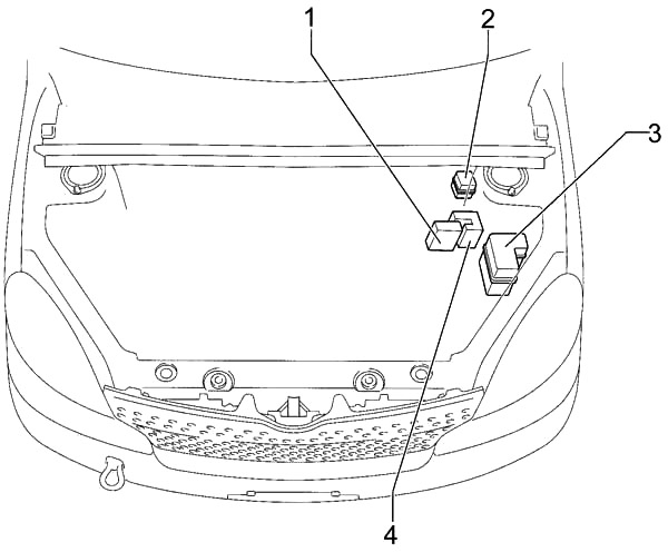
- Fusible Link Block
- Additional Fuse Box
- Fuse Box
- ABS Actuator with ECU
Engine Compartment Fuse Box Diagram
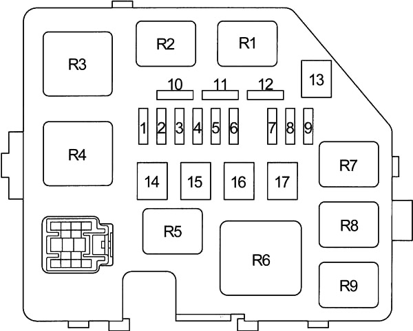
| № | Fuse | A | Circuit |
|---|---|---|---|
| 1 | DOME | 15 | Clock, Combination Meter, Double Locking, Headlight, Interior Light, Light Reminder Buzzer, Multi Display, Radio and Player, Wireless Door Lock Control |
| 2 | EFI | 15 | ECT, Engine Control, Engine Immobiliser System |
| 3 | HORN | 15 | Horn |
| 4 | AM2 | 15 | Charging, Combination Meter, ECT, Engine Control, Multi Display, SRS, Starting and Ignition |
| 5 | ST | 30 | Starting and Ignition |
| 6 | - | - | Not used |
| 7 | H−LP LH or H−LP LO LH | 10 | Left−hand Headlight, Headlight Beam Level Control (with Daytime Running Light) |
| 8 | H−LP RH or H−LP LO RH | 10 | Right−hand Headlight, Headlight Beam Level Control (with Daytime Running Light) |
| 9 | P/POINT | 15 | Power Outlet |
| 10 | - | - | Spare |
| 11 | - | - | Spare |
| 12 | - | - | Spare |
| 13 | - | - | - |
| 14 | - | - | Not used |
| 15 | RDI | 30 | Radiator Fan and Condenser Fan |
| 16 | HTR SUB1 | 50 | PTC Heater |
| 17 | - | - | Not used |
| R1 | Electric cooling fan | ||
| R2 | Electric cooling fan | ||
| R3 | Starter | ||
| R4 | Not used | ||
| R5 | Power Outlet | ||
| R6 | PTC Heater | ||
| R7 | EFI | ||
| R8 | Magnetic clutch (A/C) | ||
| R9 | Horn | ||
Advertisements
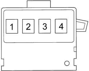
Additional Fuse Box
| № | Fuse | A | Circuit |
|---|---|---|---|
| 1 | H-LP HI RH | 10 | Headlight (with Daytime Running Light) |
| 2 | H-LP HI LH | 10 | Combination Meter, Headlight (with Daytime Running Light) |
| R1 | Headlight | ||
| R2 | Dimmer (DIM) | ||
| R3 | Not used | ||
Fusible Link Block
| № | Fuse | A | Circuit |
|---|---|---|---|
| 1 | MAIN | 60 | "EFI”, "DOME”, "HORN”, "ST”, "AM2”, "H−LP LH”, "H−LP RH”, "H−LP LH (HI)”, "H−LP RH (HI)”, "H−LP LH (LO)” and "H−LP RH (LO)” fuses |
| 2 | - | - | Not used |
| 3 | ALT | 120 | "ECU−B”, "TAIL”, "D/L”, "OBD”, "RDI”, "AM1”, "HAZ”, "HTR”, "HTR-SUB1”, "POWER”, "STOP” and "DEF” fuses |
| 4 | ABS | 60 | Anti−lock brake system |
Advertisements