
Advertisements
Fuse box diagram (fuse layout), location, and assignment of fuses and relays Toyota Yaris (XP130, XP140) (2010, 2011, 2012, 2013, 2014, 2015, 2016, 2017).

Checking and Replacing Fuses
The fuses are designed to blow before the entire wiring harness is damaged. If any of the electrical components do not operate, a fuse may have blown. If this happens, check and replace the fuses as necessary.
- Turn the engine switch off (with a smart key system – turn the “ENGINE START STOP” switch off) and turn off all electrical accessories.
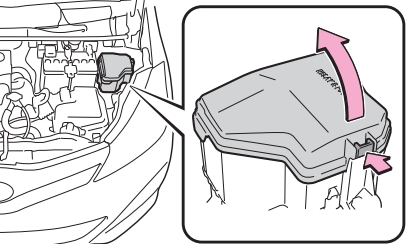
- Open the fuse box cover.
- See diagrams below for details about which fuse to check.
- Remove the fuse.
- Check if the fuse is blown – if the thin wire inside is broken, the fuse has blown.
- Replace the blown fuse with a new fuse of an appropriate amperage rating.
Notice
- Never use a fuse of a higher amperage rating than that indicated, or use any other object in place of a fuse, even as a temporary fix. This can cause extensive damage or even fire.
- Always use a genuine Toyota fuse or equivalent.
- Do not modify the fuses or fuse boxes.
- If the replaced fuse blows again, have the vehicle inspected by any authorized Toyota dealer or repairer, or another duly qualified and equipped professional.
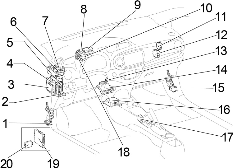
Passenger Compartment
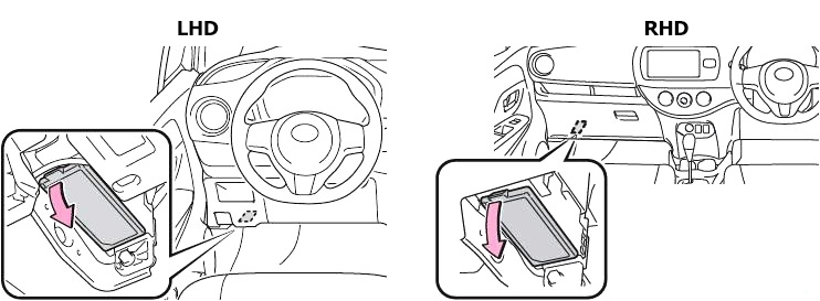
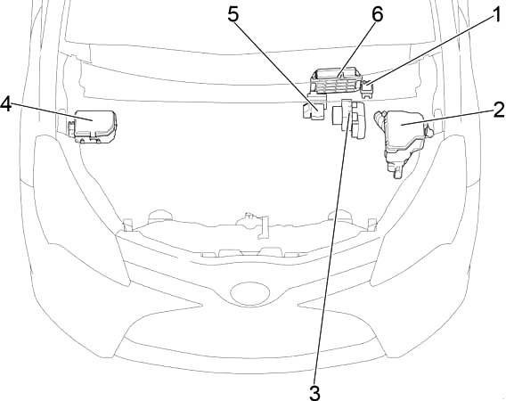
Left-hand drive
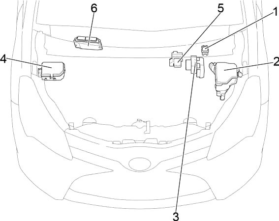
Right-hand drive
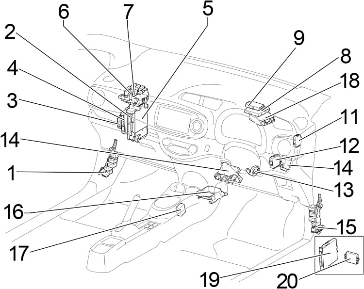
- Junction Block
- Fuse Box
- Power Management Control ECU (without Stop & Start System)
- Engine Stop and Start ECU
- Main Body ECU
- Heater Relay (HTR)
- Relay Box
- Driving Support ECU Assembly
- Power Management Control ECU (with Stop & Start System)
- Transmission Control ECU Assembly (LHD)
- Network Gateway ECU
- Windshield Wiper Relay Assembly
- Transponder Key Amplifier
- A/C Amplifier Assembly
- Junction Block
- Airbag Sensor Assembly
- Shift Lock Control Unit Assembly
- Power Steering ECU Assembly
- Certification ECU Assembly
- ID Code Box (with Entry & Start System)
Transponder Key ECU Assembly (without Entry & Start System)
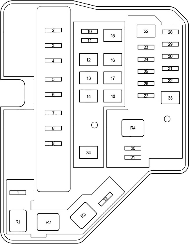
Passenger Compartment Fuse Box Diagram
The fuse panel is located under the left side of the dashboard. Remove the lid.
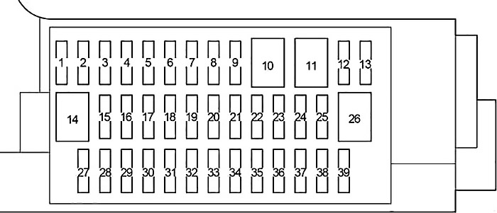
| № | Fuse | A | Circuit |
|---|---|---|---|
| 1 | - | - | - |
| 2 | - | - | - |
| 3 | - | - | - |
| 4 | S-HTR | 15 | Seat heater |
| 5 | - | - | - |
| 6 | - | - | - |
| 7 | ECU-B №3 | 7.5 | Remote control mirror (with automatic retractable mirror) |
| 8 | - | - | - |
| 9 | - | - | - |
| 10 | - | - | - |
| 11 | - | - | - |
| 12 | D-D/L | 25 | Double locking |
| 13 | - | - | - |
| 14 | - | - | - |
| 15 | FOG FR | 15 | before Jan. 2013: Front fog lights |
| from Jan. 2013 (TMC made): Front fog lights (TMC - Toyota Motor Corporation) | |||
| 7.5 | from Jan. 2013 (TMMF made): Front fog lights (TMMF - Toyota Motor Manufacturing France) | ||
| 16 | AM1 | 7.5 | Starting system, engine switch |
| 17 | STOP | 7.5 | Multiport fuel injection system/sequential multiport fuel injection system, vehicle stability control system, stop lights, high mounted stoplight |
| 18 | FOG RR | 7.5 | Rear fog lights |
| 19 | - | - | - |
| 20 | OBD | 7.5 | On-board diagnosis system |
| 21 | D/L | 25 | Power door lock system, main body ECU |
| 22 | ACC | 5 | Main body ECU, outside rear view mirrors, audio system, shift lock control system |
| 23 | CIG | 15 | Power outlets |
| 24 | DOOR | 20 | Power windows |
| 25 | DOOR R/L | 20 | Power windows |
| 26 | P/W | 30 | Power windows |
| 27 | WIPER RR | 15 | Rear window wiper |
| 28 | WIPER | 20 | Windshield wiper |
| 29 | WASHER | 15 | Windshield washer |
| 30 | - | - | - |
| 31 | - | - | - |
| 32 | GAUGE | 10 | Back-up lights, shift lock control system, audio system, charging system, multiport fuel injection system/sequential multiport fuel injection system |
| 33 | A/C | 7.5 | Air conditioning system, rear window defogger, outside rear view mirror defoggers |
| 34 | ECU-IG №2 | 5 | Vehicle stability control system |
| 35 | ECU-IG №1 | 5 | Electric cooling fan, rear window defogger, vehicle stability control system, electric power steering system, main body ECU, wireless remote control system, tire pressure warning system |
| 36 | DOOR P | 20 | Power windows |
| 37 | DOOR R/R | 20 | Power windows |
| 38 | PANEL | 5 | Gauges and meters, instrument panel lights, switch illumination |
| 39 | TAIL №2 | 10 | Parking lights, tail lights, license plate lights, side marker lights |
Relay Box
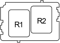
| № | Relay |
|---|---|
| R1 | DOME CUT |
| R2 | before Jul. 2014: Front fog lights (FR FOG) |
| from May 2015: (STP) |
Advertisements
Engine Compartment
Left-hand drive
Right-hand drive
- Glow Plug Relay Assembly
- Fuse Box
- Brake Actuator Assembly (TMC Made)
ABS & Traction Actuator Assembly (TMMF Made) - Fuse Box №2
- Fusible Link Block Assembly
- ECM
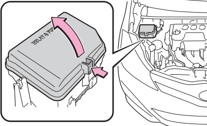
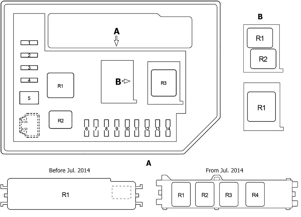
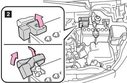
Engine Compartment Fuse Box №1
Push the tab in and lift the lid off.
| № | Fuse | A | Circuit |
|---|---|---|---|
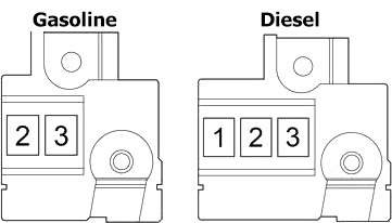
| 1 | ID/UP | 7.5 | Multiport fuel injection system/sequential multiport fuel injection system |
| 2 | EFI MAIN | 20 | Gasoline: Multiport fuel injection system/sequential multiport fuel injection system |
| ECD MAIN | 30 | Diesel: Multiport fuel injection system/sequential multiport fuel injection system | |
| 3 | EFI №3 | 7.5 | Multiport fuel injection system/sequential multiport fuel injection system |
| 4 | HORN | 10 | Horn |
| 5 | EFI №2 | 10 | Multiport fuel injection system/sequential multiport fuel injection system |
| 6 | IG2 | 10 | Multiport fuel injection system/sequential multiport fuel injection system, airbag system, stop lights, front passenger occupant classification system |
| 7 | IGN | 15 | Multiport fuel injection system/sequential multiport fuel injection system |
| 8 | MET | 7.5 | Gauges and meters |
| 9 | - | - | - |
| 10 | PTC HTR №3 | 30 | from Jul. 2014 (TMMF): PTC heater (TMMF - Toyota Motor Manufacturing France) |
| 11 | PWR HTR | 25 | before Jul. 2014 (TMMF): PTC heater (TMMF - Toyota Motor Manufacturing France) |
| PTC HTR №2 | 30 | from Jul. 2014 (TMMF): PTC heater (TMMF - Toyota Motor Manufacturing France) | |
| 12 | EPS | 50 | Electric power steering system |
| 13 | ABS №2 | 30 | Anti-lock brake system, vehicle stability control system |
| 14 | DEF | 30 | Rear window defogger, outside rear view mirror defoggers |
| 15 | HTR | 40 | Air conditioning system |
| 16 | PTC HTR №1 | 50 | TMMF: PTC heater (TMMF - Toyota Motor Manufacturing France) |
| H-LP CLN | 30 | ||
| 17 | RDI FAN | 30 | Electric cooling fan |
| 18 | ABS №1 | 50 | Anti-lock brake system, vehicle stability control system |
| 19 | MIR-HTR | 10 | Mirror heater, rear window defogger, cruise control, cvt and shift indicator, engine control |
| 20 | ECU-B №1 | 5 | Multiport fuel injection system/sequential multiport fuel injection system, main body ECU |
| 21 | DOME | 15 | Interior light, personal lights, audio system, vehicle stability control system |
| 22 | BBC | 40 | Charging (1NR-FE), stop & start system |
| 23 | ST | 30 | Starting system |
| 24 | AMP | 15 | TMMF: Audio system, navigation system, parking assist (rear view monitor) (TMMF - Toyota Motor Manufacturing France) |
| 25 | D/L №2 | 25 | before Jul. 2014: Double locking |
| PWR HTR | 25 | before Jul. 2014 (TMMF): Power heater (TMMF - Toyota Motor Manufacturing France) | |
| 26 | D.C.C | 30 | DOME, ECU-B №1, ECU-B №2 |
| 27 | STR LOCK | 20 | before Jul. 2014 (TMMF): Back door opener, engine immobiliser system, entry & start system, starting, steering lock, wireless door lock control (TMMF - Toyota Motor Manufacturing France) |
| 28 | ETCS | 10 | Multiport fuel injection system/sequential multiport fuel injection system |
| 29 | HAZ | 10 | Turn signal lights, emergency flashers |
| 30 | AM2 | 7.5 | Multiport fuel injection system/sequential multiport fuel injection system, starting system |
| 31 | ECU-B №2 | 5 | Gauges and meters, wireless remote control system, tire pressure warning system, front passenger occupant classification system |
| 32 | ALT-S | 7.5 | Charging system |
| 33 | R/I | 50 | EFI MAIN, EFI №2, EFI №3, IG2, IGN, MET, HORN |
| 34 | PTC | 80 | PTC heater, outside rear view mirror defoggers |
| R1 | Electric cooling fan (FAN №2) | ||
| R2 | Electric cooling fan (FAN №1) | ||
| R3 | Rear window defogger (DEF) | ||
| R4 | Starter (ST) | ||
Advertisements
Engine Compartment Fuse Box №2
Push the tab in and lift the lid off.
| № | Fuse | A | Circuit |
|---|---|---|---|
| 1 | ST №2 | 20 | Cruise control (1NR-FE), CVT and shift indicator (1NR-FE), engine control (1NR-FE), starting |
| 2 | DRL | 7.5 | Daytime running light system |
| EU-DRL | 15 | Daytime running light system | |
| 3 | ECD №4 | 10 | Cooling fan, cruise control (1ND-TV), engine control (1ND-TV) |
| S-HORN | 10 | Multiport fuel injection system/sequential multiport fuel injection system | |
| 4 | H-LP MAIN | 7.5 | before Jul. 2014: Air conditioner (except automatic a/c), automatic light control, headlight beam level control, light auto turn off system |
| 20 | from Jul. 2014: Air conditioner (except automatic a/c), automatic light control, headlight, headlight beam level control, light auto turn off system | ||
| 5 | MMT | 50 | Multi-mode manual transmission |
| 6 | H-LP RH HI | 10 | Right-hand headlight (high beam) |
| 7 | H-LP LH HI | 10 | Left-hand headlight (high beam), gauges and meters |
| 8 | H-LP RH LO | 10 | Right-hand headlight (low beam) |
| 9 | H-LP LH LO | 10 | Left-hand headlight (low beam), front fog lights |
| 10 | - | - | - |
| 11 | - | - | - |
| 12 | - | - | - |
| 13 | - | - | - |
| 14 | - | - | - |
| R1 | before Jul. 2014: Dimmer (DIM) | ||
| from Jul. 2014: PTC heater (PTC HTR №1) | |||
| R2 | Daytime running light system (DRL/S-HORN) | ||
| R3 | Headlights (H-LP) | ||
| Headlights (H-LP/US-DRL) | |||
| R1 | Integration relay | ||
| R1 | ECD №2 | ||
| R2 | PTC HTR №2 | ||
| R3 | PTC HTR №3 | ||
| R4 | ST №2 | ||
| R1 | - | ||
| R2 | before Jul. 2014: (O/P MTR (with Stop & Start System)) | ||
| from Jul. 2014: Dimmer (DIM (Projector Headlight)) | |||
| R1 | before Jul. 2014: Multi-mode manual transmission (MMT) | ||
| from Jul. 2014: Dimmer (DIM) | |||
Fusible Link Block
1. Pull the rubber strip on the edge to unhook it from the cover, and then push the tabs in and lift the cover off.
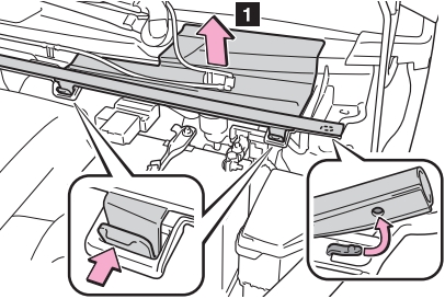
2. Remove the battery terminal cover and then the fuse box cover.
| № | Fuse | A | Circuit |
|---|---|---|---|
| 1 | GLOW DC/DC | 80 | Multiport fuel injection system/sequential multiport fuel injection system |
| 2 | MAIN | 80 | "BBC", "ST", "AMP", "D/L №2", "D.C.C", "STR LOCK", "MIR-HTR", "ETCS", "HAZ", "AM2", "ALT-S", "R/I", "DRL" "EU-DRL", "S-HORN", "H-LP MAIN", "H-LP RH HI", "H-LP LH HI", "H-LP RH LO", "H-LP LH LO" fuses |
| 3 | ALT | 120 | "ID/UP", "EPS", "ABS №2", "DEF", "PTC", "HTR", "H-LP CLN", "RDI FAN", "ABS №1", "TAIL №2", "PANEL", "DOOR R/R", "DOOR P", "ECU-IG №1", "ECU-IG №2", "A/C", "GAUGE", "WASHER", "WIPER", "WIPER RR", "P/W", "DOOR R/L", "DOOR", "CIG", "ACC", "D/L", "OBD", "STOP", "AM1", "FOG FR" fuses |
Advertisements