
Advertisements
Fuse box diagram (fuse layout), location, and assignment of fuses and relays Toyota Verso-S (NCP120) (2010, 2011, 2012, 2013, 2014, 2015, 2016, 2017).
Checking and Replacing Fuses
The fuses are designed to blow before the entire wiring harness is damaged. If any of the electrical components do not operate, a fuse may have blown. If this happens, check and replace the fuses as necessary.
- Turn the engine switch off (with a smart key system – turn the “ENGINE START STOP” switch off) and turn off all electrical accessories.
- Open the fuse box cover.
- See diagrams below for details about which fuse to check.
- Remove the fuse.
- Check if the fuse is blown – if the thin wire inside is broken, the fuse has blown.
- Replace the blown fuse with a new fuse of an appropriate amperage rating.
Notice
- Never use a fuse of a higher amperage rating than that indicated, or use any other object in place of a fuse, even as a temporary fix. This can cause extensive damage or even fire.
- Always use a genuine Toyota fuse or equivalent.
- Do not modify the fuses or fuse boxes.
- If the replaced fuse blows again, have the vehicle inspected by any authorized Toyota dealer or repairer, or another duly qualified and equipped professional.
Passenger Compartment
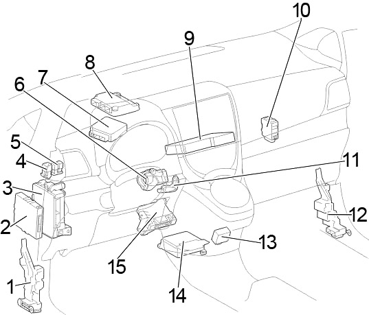
Left-hand drive
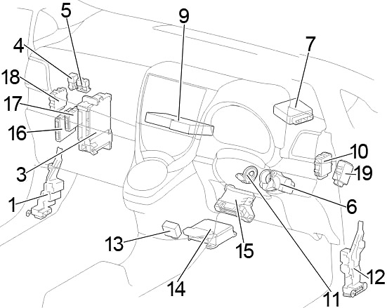
Right-hand drive
- Junction Block
- LHD:
Engine Stop and Start ECU
without Stop & Start System: Power Management Control ECU - Fuse Box / Main Body ECU
- Heater Relay (HTR)
- Relay Box
- Steering Lock Actuator
- Power Steering ECU
- Transmission Control ECU
- Extension Module
- Windshield Wiper Relay
- Transponder Key Amplifier
- Junction Block
- Shift Lock Control ECU
- Center Airbag Sensor
- A/C Amplifier
- RHD: Engine Stop and Start ECU
- RHD: Power Management Control ECU
- RHD: Headlight Leveling ECU
- RHD: Double Lock Door Control Relay
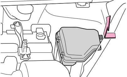
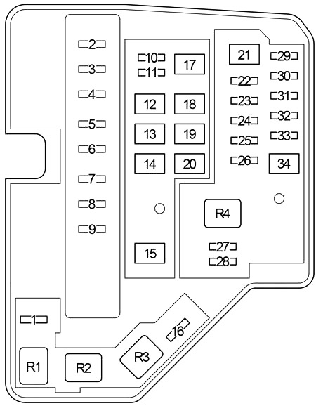
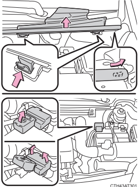
Passenger Compartment Fuse Box Diagram
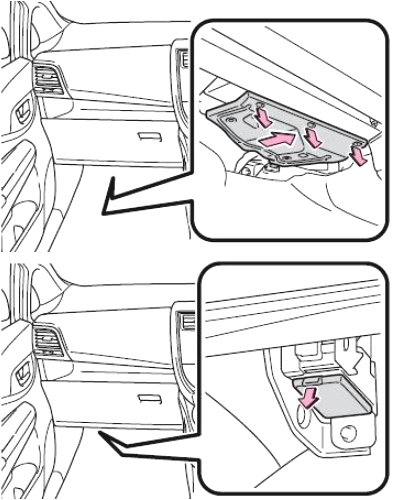
The fuse panel is located under the left side of the dashboard.
Left-hand drive: Remove the lid.
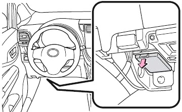
Right-hand drive: Remove the cover and then remove the lid (Do not pull off the cover using excessive force as it is attached to the footwell light).
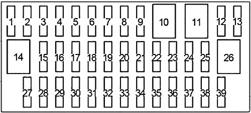
| № | Fuse | A | Circuit |
|---|---|---|---|
| 1 | - | - | - |
| 2 | - | - | - |
| 3 | - | - | - |
| 4 | S-HTR | 15 | Seat heaters |
| 5 | - | - | - |
| 6 | - | - | - |
| 7 | - | - | - |
| 8 | SHADE | 25 | Panoramic roof shade |
| 9 | - | - | - |
| 10 | - | - | - |
| 11 | - | - | - |
| 12 | D-D/L | 25 | Multiport fuel injection system/sequential multiport fuel injection system |
| 13 | - | - | - |
| 14 | - | - | - |
| 15 | FOG FR | 15 | Front fog lights, gauge and meters |
| 16 | AM1 | 7.5 | Starting system |
| 17 | STOP | 7.5 | Multiport fuel injection system/sequential multiport fuel injection system, smart entry & start system, ABS, VSC, multi-mode manual transmission, stop lights, high mounted stoplight, shift lock control system |
| 18 | FOG RR | 7.5 | Rear fog light, gauge and meters |
| 19 | - | - | - |
| 20 | OBD | 7.5 | On-board diagnosis system |
| 21 | D/L | 25 | Power door lock system |
| 22 | ACC | 5 | Main body ECU, outside rear view mirrors, audio system, Stop & Start system, shift lock control system |
| 23 | CIG | 15 | Power outlets |
| 24 | DOOR | 20 | Power windows |
| 25 | DOOR R/L | 20 | Power windows |
| 26 | P/W | 30 | Power windows |
| 27 | WIPER RR | 15 | Rear window wiper |
| 28 | WIPER | 20 | Windshield wipers |
| 29 | WASHER | 15 | Windshield washer |
| 30 | - | - | - |
| 31 | - | - | - |
| 32 | GAUGE | 10 | Back-up light, shift lock control system, rear seat belt reminder lights, auto anti-glare inside rear view mirror, multidrive, audio system, panoramic roof shade, multiport fuel injection system/sequential multiport fuel injection system, rain sensor |
| 33 | A/C | 7.5 | Air conditioning system, power heater, rear window defogger, outside rear view mirror defoggers |
| 34 | ECU-IG №2 | 5 | ABS, VSC, Stop & Start system |
| 35 | ECU-IG №1 | 5 | Electric cooling fan, rear window defogger, electric power steering, main body ECU, windshield wipers, VSC |
| 36 | DOOR P | 20 | Power windows |
| 37 | DOOR R/R | 20 | Power windows |
| 38 | PANEL | 5 | Gauge and meters, instrument panel lights, switch illumination |
| 39 | TAIL №2 | 10 | Front position lights, tail lights, license plate lights, front fog lights, rear fog light, multiport fuel injection system/sequential multiport fuel injection system, gauge and meters |
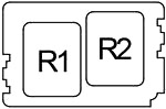
Relay Box
| № | Relay |
|---|---|
| R1 | - |
| R2 | Front fog light (FR FOG) |
Advertisements
Engine Compartment
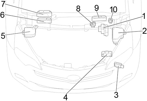
- Skid Control ECU with Actuator
- Fuse Box
- Fuel Pump Control ECU
- ECO Run Vehicle Converter
- Fuse Box №2
- LHD 1NR-FE: ECM
- LHD 1ND-TV: ECM
- Fusible Link Block
- RHD: ECM
- Glow Plug Relay
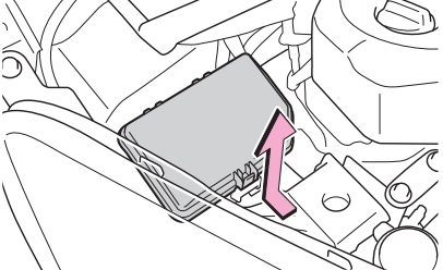
Engine Compartment Fuse Box №1
Push the tab in and lift the lid off.
| № | Fuse | A | Circuit |
|---|---|---|---|
| 1 | ID/UP | 7.5 | Multiport fuel injection system/sequential multiport fuel injection system |
| 2 | EFI MAIN | 20 | Gasoline: Multiport fuel injection system/sequential multiport fuel injection system |
| ECD MAIN | 30 | Diesel: Multiport fuel injection system/sequential multiport fuel injection system, "EFI №2" fuse | |
| 3 | EFI №3 | 7.5 | Multiport fuel injection system/sequential multiport fuel injection system |
| 4 | HORN | 10 | Horn |
| 5 | EFI №2 | 10 | Stop & Start system, multiport fuel injection system/sequential multiport fuel injection system |
| 6 | IG2 | 10 | Smart entry & start system, multiport fuel injection system/sequential multiport fuel injection system, multi-mode manual transmission, SRS airbag system, steering lock system, stop lights, Stop & Start system |
| 7 | IGN | 15 | Multiport fuel injection system/sequential multiport fuel injection system |
| 8 | MET | 7.5 | Gauge and meters, Stop & Start system |
| 9 | - | - | - |
| 10 | - | - | - |
| 11 | PWR HTR | 25 | Power heater, multiport fuel injection system/sequential multiport fuel injection system |
| 12 | EPS | 50 | Electric power steering |
| 13 | ABS №2 | 30 | ABS, VSC |
| 14 | DEF | 30 | Rear window defogger |
| 15 | PTC | 80 | PTC heater, outside rear view mirror defoggers |
| 16 | - | - | - |
| 17 | HTR | 40 | Air conditioning system |
| 18 | - | - | - |
| 19 | RDI FAN | 30 | Electric cooling fan |
| 20 | ABS №1 | 50 | ABS, VSC |
| 21 | BBC | 40 | Stop & Start system |
| 22 | ST | 30 | Starting system |
| 23 | - | - | - |
| 24 | D/L №2 | 25 | Power door lock |
| 25 | D.C.C | 30 | "DOME", "ECU-B №1" fuses |
| 26 | STR LOCK | 20 | Steering lock system |
| 27 | ECU-B №1 | 5 | Main body ECU, smart entry & start system |
| 28 | DOME | 15 | Interior lights, audio system, VSC |
| 29 | ETCS | 10 | Multiport fuel injection system/sequential multiport fuel injection system |
| 30 | HAZ | 10 | Turn signal lights |
| 31 | AM2 | 7.5 | Multiport fuel injection system/sequential multiport fuel injection system, smart entry & start system, starting system, multi-mode manual transmission |
| 32 | ECU-B №2 | 5 | Gauge and meters, power door lock, wireless remote control, Stop & Start system, smart entry & start system, multi-mode manual transmission, air conditioning system |
| 33 | - | - | - |
| 34 | R/I | 50 | "EFI MAIN", "ECD MAIN", "EFI №2", "EFI №3", "IG2", "IGN", "MET", "HORN" fuses |
| R1 | Electric cooling fan (FAN №2) | ||
| R2 | Electric cooling fan (FAN №1) | ||
| R3 | Rear window defogger (DEF) | ||
| R4 | Starting system (ST) | ||
| with Stop & Start System; 1NZ-FE: Starting system (ST2) | |||
Advertisements
Engine Compartment Fuse Box №2
Push the tab in and lift the lid off.
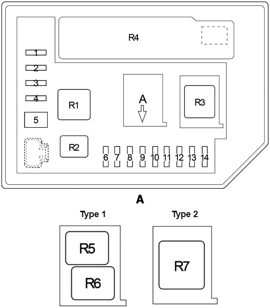
| № | Fuse | A | Circuit |
|---|---|---|---|
| 1 | - | - | - |
| 2 | EU-DRL | 15 | Headlight |
| 3 | S-HORN | 10 | Multiport fuel injection system/sequential multiport fuel injection system |
| 4 | H-LP MAIN | 7.5 | "H-LP RH LO", "H-LP LH LO" fuses |
| 5 | MMT | 50 | Multi-mode manual transmission |
| ST | 40 | with Stop & Start System; 1NZ-FE: Starting system | |
| 6 | H-LP RH HI | 10 | Right-hand headlight (high beam) |
| 7 | H-LP LH HI | 10 | Left-hand headlight (high beam), gauge and meters |
| 8 | H-LP RH LO | 10 | Halogen: Right-hand headlight (low beam) |
| 15 | HID: Right-hand headlight (low beam) | ||
| 9 | H-LP LH LO | 10 | Halogen: Left-hand headlight (low beam), manual headlight leveling dial |
| 15 | HID: Left-hand headlight (low beam), manual headlight leveling dial | ||
| 10 | - | - | - |
| 11 | - | - | - |
| 12 | - | - | - |
| 13 | - | - | - |
| 14 | - | - | - |
| R1 | Dimmer (DIM) | ||
| R2 | Daytime running lights / Theft deterrent (EU-DRL/S-HORN) | ||
| R3 | Headlight / Daytime running lights (H-LP/US-DRL) | ||
| R4 | Integration Relay | ||
| R5 | 1NR-FE, 1ND-TV: Daytime running lights (DRL) | ||
| with Stop & Start System 1NZ-FE: Starter ((ST) Before May 2014) | |||
| R6 | 1NR-FE, 1ND-TV: (O/P MTR) | ||
| R7 | Multi-mode manual transmission (MMT) | ||
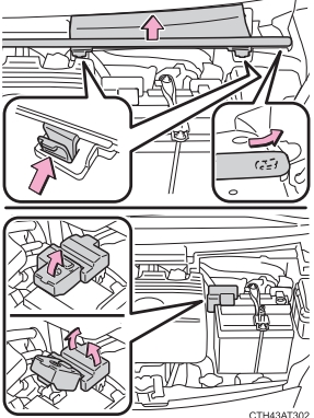
Fusible Link Block
Pull the rubber strip on the edge to unhook it from the cover, and then push the tabs in and lift the cover off. Remove the battery terminal cover and then the fuse box cover.
Left-hand drive
Right-hand drive
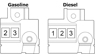
| № | Fuse | A | Circuit |
|---|---|---|---|
| 1 | GLOW DC/DC | 80 | Engine glow system |
| 2 | MAIN | 80 | "BBC", "S-HORN", "ST", "D/L №2", "D.C.C.", "STR LOCK", "ETCS", "HAZ", "AM2", "ECU-B №2", "R/I", "H-LP MAIN", "H-LP RH HI", "H-LP LH HI", "H-LP RH LO", "H-LP LH LO", "MMT" fuses |
| 3 | ALT | 120 | "PWR HTR", "EPS", "ABS №2", "DEF", "PTC", "HTR", "RDI FAN", "ABS №1", "TAIL №2", "PANEL", "DOOR R/R", "DOOR P", "ECU-IG №1", "ECU-IG №2", "A/C", "GAUGE", "WASHER", "WIPER", "WIPER RR", "P/W", "DOOR R/L", "DOOR", "CIG", "ACC", "D/L", "OBD", "FOG RR", "STOP", "AM1", "FOG FR", "D-D/L", "SHADE", "S-HTR" fuses |
Advertisements