
Advertisements
Fuse box diagram (fuse layout), location, and assignment of fuses and relays Toyota RAV4 (XA30) (2006, 2007, 2008, 2009, 2010, 2011, 2012).

Checking and Replacing Fuses
The fuses are designed to blow before the entire wiring harness is damaged. If any of the electrical components do not operate, a fuse may have blown. If this happens, check and replace the fuses as necessary.
- Turn the engine switch off (with a smart key system – turn the “ENGINE START STOP” switch off) and turn off all electrical accessories.
- Open the fuse box cover.
- See diagrams below for details about which fuse to check.
- Remove the fuse.
- Check if the fuse is blown – if the thin wire inside is broken, the fuse has blown.
- Replace the blown fuse with a new fuse of an appropriate amperage rating.
Notice
- Never use a fuse of a higher amperage rating than that indicated, or use any other object in place of a fuse, even as a temporary fix. This can cause extensive damage or even fire.
- Always use a genuine Toyota fuse or equivalent.
- Do not modify the fuses or fuse boxes.
- If the replaced fuse blows again, have the vehicle inspected by any authorized Toyota dealer or repairer, or another duly qualified and equipped professional.
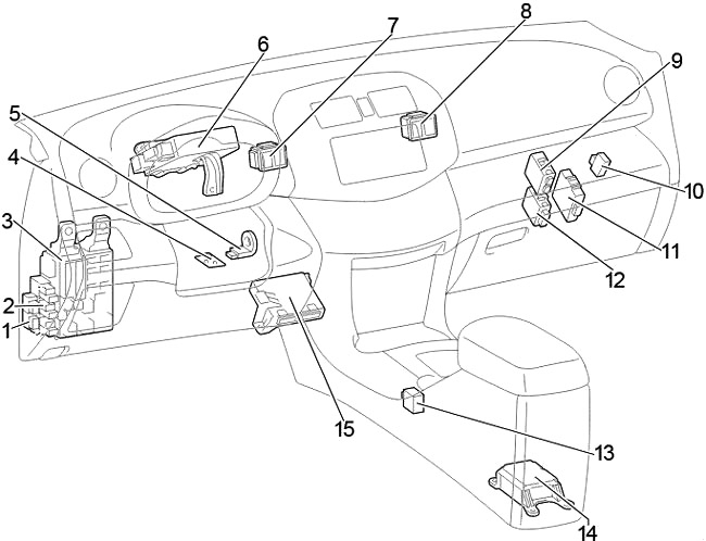
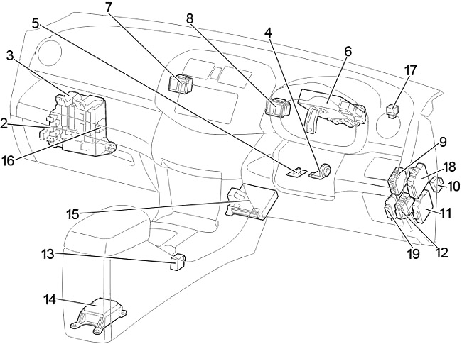
Passenger Compartment
Left-hand drive
Right-hand drive
- LHD: Panel Relay
- Relay Box
- Fuse Box / Main Body ECU
- Transponder Key Amplifier
- Steering Lock ECU
- Power Steering ECU
- Junction Block №3
- Junction Block №4
- Tire Pressure Warning ECU
- Stop Light Control Relay
- 4WD Control ECU
- Auto Wiper Relay
- Shift Lock Control ECU
- Airbag Sensor Assembly Center
- A/C Amplifier
- RHD: Starter Relay (ST) (Gasoline, Before Dec. 2008:Diesel with Entry & Start System)
Short Pin (Before Dec. 2008: Diesel without Entry & Start System) - RHD: Turn Signal Flasher
- RHD: Theft Warning ECU
- RHD: Double Locking ECU
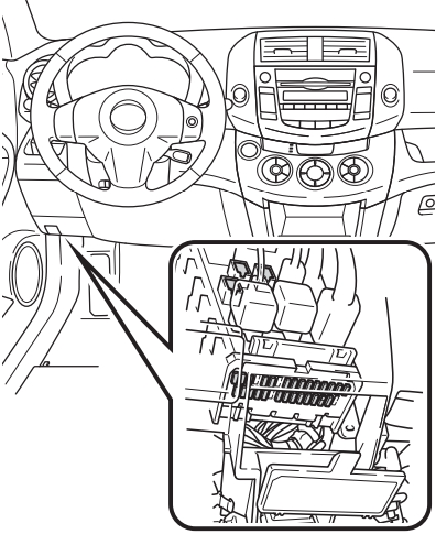
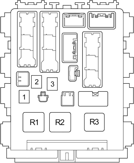
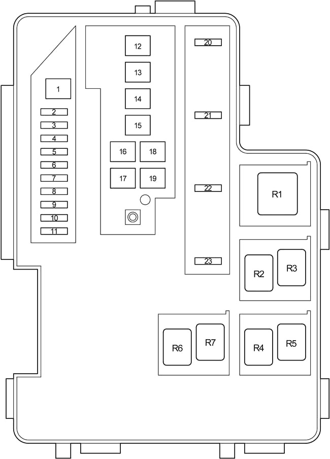
Passenger Compartment Fuse Box Diagram
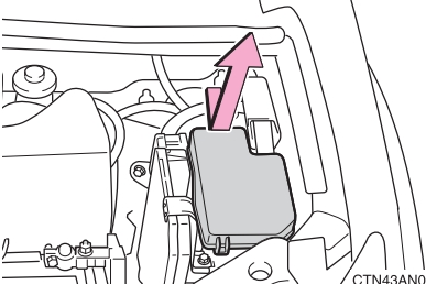
The fuse panel is located under the left side of the dashboard. Remove the lid (RHD: remove the cover under glove box first).
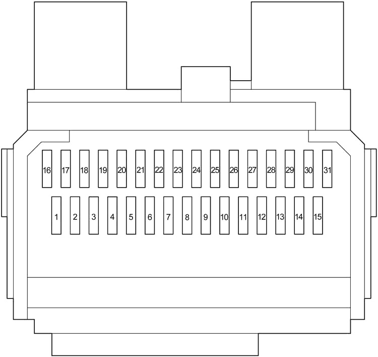
| № | Fuse | A | Circuit |
|---|---|---|---|
| 1 | - | - | Not used |
| 2 | S−HTR | 15 | Seat heaters |
| 3 | WIP | 25 | Windshield wipers |
| 4 | RR WIP | 15 | Rear window wiper |
| 5 | WSH | 15 | Windshield washer, rear window washer |
| 6 | ECU−IG1 | 10 | Electric cooling fans, anti−lock brake system, traction control system, vehicle stability control system, downhill assist control system, hill−start assist control system, Active Torque Control 4WD system, automatic transmission shift lock system, air conditioning system, main body ECU, electric moon roof, windshield wiper de-icer, stop/tail lights, electric power steering system, clock, auto anti-glare inside rear view mirror |
| 7 | ECU-IG2 | 10 | Air conditioning system, rear window defogger |
| 8 | OBD | 7.5 | On-board diagnosis system |
| 9 | STOP | 10 | Stop/tail lights, high mounted stoplight, automatic transmission shift lock system, multiport fuel injection system/sequential multiport fuel injection system, anti-lock brake system, traction control system, vehicle stability control system, downhill assist control system, hill-start assist control system |
| 10 | - | - | Not used |
| 11 | DOOR | 25 | Main body ECU, power door lock system |
| 12 | ACC-B | 25 | "ACC", "CIG" fuses |
| 13 | 4WD | 7.5 | Active Torque Control 4WD system |
| 14 | FR FOG | 15 | Front fog lights |
| 15 | AM1 | 7.5 | Starting system |
| 16 | TAIL | 10 | Tail lights, parking lights, license plate light, front fog lights, rear fog lights |
| 17 | PANEL | 7.5 | Clock, instrument panel lights, audio system |
| 18 | GAUGE1 | 10 | Buck−up lights, charging system |
| 19 | D FR DOOR | 20 | Power windows (front doors) |
| 20 | RL DOOR | 20 | Power windows |
| 21 | RR DOOR | 20 | Power windows |
| 22 | S/ROOF | 25 | Electric moon roof |
| 23 | CIG | 15 | Cigarette lighter |
| 24 | ACC | 7.5 | Audio system, power outlets, power rear view mirror control, automatic transmission shift lock system, main body ECU, clock |
| 25 | - | - | Not used |
| 26 | MIR HTR | 10 | Outside rear view heaters |
| 27 | PWR OUTLET | 15 | Power outlets |
| 28 | - | - | Not used |
| 29 | RR FOG | 10 | Rear fog light |
| 30 | IGN | 7.5 | SRS airbag system, multiport fuel injection system/sequential multiport fuel injection system, stop/tail lights, starting system |
| 31 | GAUGE2 | 7.5 | Meters and gauges |
Advertisements
| № | Fuse | A | Circuit |
|---|---|---|---|
| 1 | POWER | 30 | Power windows |
| 2 | DEF | 30 | Rear window defogger, "MIR HTR” fuse |
| 3 | P/SEAT | 30 | Power seat |
| R1 | Ignition (IG1) | ||
| R2 | Heater (Manual A/C) | ||
| Short Pin (Automatic A/C) | |||
| R3 | LHD: Turn Signal Flasher | ||
Relay Box
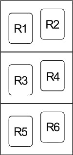
| № | Relay |
|---|---|
| R1 | Starter (ST CUT) |
| R2 | LHD: Starter (ST) (Gasoline, Before Dec. 2008: Diesel with Entry & Start System) |
| LHD: Short Pin (Before Dec. 2008: Diesel without Entry & Start System) | |
| R3 | Front fog light (FR FOG) |
| R4 | Rear fog light (RR FOG) |
| Power Outlet (115V) | |
| R5 | Accessory (ACC) |
| R6 | Power outlet (PWR OUTLET) |
Engine Compartment
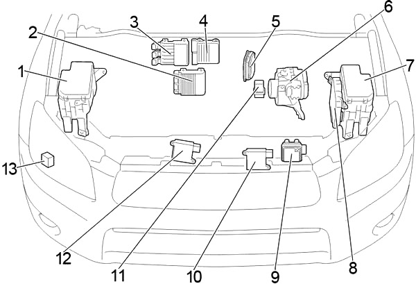
- Fuse Box (№1)
- 2AD-FHV, 2AD-FTV: Injector Driver (EDU) (From Dec. 2008; Europe)
- 2AD-FHV: Injector Driver (EDU) (Before Dec. 2008; Europe)
- 2AD-FTV: Injector Driver (EDU) (Before Dec. 2008; Europe)
- Valve Lift Control Driver
- Skid Control ECU with Actuator
- Fuse Box (№2)
- Engine Control Module
- Transmission Control ECU
- Cooling Fan ECU or Cooling Fan ECU (LH)
- Glow Plug Relay
- Cooling Fan ECU (RH)
- Headlamp Cleaner Control Relay
Advertisements
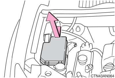
Engine Compartment Fuse Box №1
Push the tab in and lift the lid off.
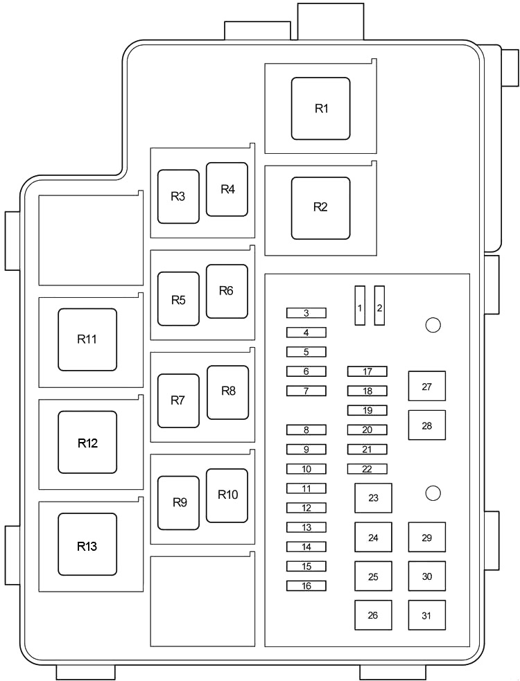
| № | Fuse | A | Circuit |
|---|---|---|---|
| 1 | - | - | Not used |
| 2 | - | - | Not used |
| 3 | - | - | Not used |
| 4 | ECU-B2 | 7.5 | Air conditioning system, power windows |
| 5 | ALT−S | 7.5 | Charging system |
| RSE | 7.5 | Audio System (JBL) | |
| 6 | STR LOCK | 20 | No circuit |
| 7 | - | - | Not used |
| 8 | DCC | - | - |
| 9 | RAD №1 | 20 | Audio system |
| 10 | ECU−B | 10 | Wireless remote control system, main body ECU, clock, meters, gauges and vehicle stability control system, electric power steering system |
| 11 | DOME | 10 | Ignition switch light, interior light, vanity lights, luggage compartment light, front personal lights, foot lights |
| 12 | - | - | - |
| 13 | HEAD LH | 10 | Left−hand headlight (high beam) |
| 14 | HEAD RH | 10 | Right−hand headlight (high beam) |
| 15 | HEAD LL | 10 | Left−hand headlight (low beam) |
| 16 | HEAD RL | 10 | Right−hand headlight (low beam) |
| 17 | - | - | - |
| 18 | AC INV | 15 | Power Outlet (115V) |
| 19 | TOWING | 30 | Trailer Towing |
| 20 | STV HTR | 25 | No circuit |
| 21 | - | - | Not used |
| 22 | DEICER | 20 | Front Window Deicer |
| 23 | HTR | 50 | Air conditioning system |
| 24 | PTC3 | 50 | PTC heater |
| 25 | PTC2 | 50 | PTC heater |
| 26 | PTC1 | 50 | PTC heater |
| 27 | HEAD MAIN | 50 | "HEAD LL”, "HEAD RL”, "HEAD LH”, "HEAD RH” fuses |
| 28 | - | - | Not used |
| 29 | RDI | 30 | without towing package (except 2GR-FE): Electric cooling fans |
| FAN2 | 50 | with towing package (2GR-FE): Electric cooling fans | |
| 30 | CDS | 30 | without towing package (except 2GR-FE): Electric cooling fans |
| FAN1 | 50 | with towing package (2GR-FE): Electric cooling fans | |
| 31 | H−LP CLN | 30 | No circuit |
| R1 | Dimmer | ||
| R2 | Headlight | ||
| R3 | Daytime running light relay (№4) | ||
| R4 | Daytime running light relay (№3) | ||
| R5 | Except 2GR-FE: Electric cooling fan (№3) | ||
| R6 | Except 2GR-FE: Electric cooling fan (№2) | ||
| R7 | Except 2GR-FE: Electric cooling fan (№1) | ||
| R8 | Not used | ||
| R9 | Front Window Deicer | ||
| R10 | Daytime running light relay (№2) | ||
| R11 | Except 2GR-FE: PTC heater (PTC №3) | ||
| R12 | Except 2GR-FE: PTC heater (PTC №2) | ||
| 2GR–FE: Electric cooling fan (№2) | |||
| R13 | 2GR–FE: Electric cooling fan (№1) | ||
| Except 2GR-FE: PTC heater (PTC №1) | |||
Advertisements
Engine Compartment Fuse Box №2
Push the tab in and lift the lid off.
| № | Fuse | A | Circuit |
|---|---|---|---|
| 1 | P-SYSTEM | 30 | 3ZR-FAE: Valve lift control driver |
| 2 | AMP | 30 | Audio System (JBL) |
| 3 | AM2 | 30 | Starting system |
| 4 | IG2 | 15 | Engine control, ignition |
| 5 | HAZ | 10 | Emergency flashers |
| 6 | ETCS | 10 | Cruise Control, Electronically Controlled Transmission and A/T Indicator, Engine Control, Engine Immobiliser System |
| 7 | AM2−2 | 7.5 | Starting system |
| 8 | - | - | - |
| 9 | EFI №1 | 10 | Multiport fuel injection system/sequential multiport fuel injection system |
| 10 | EFI №2 | 10 | Multiport fuel injection system/sequential multiport fuel injection system |
| 11 | EFI №3 | 7.5 | A/T; From Dec. 2008: Multiport fuel injection system/sequential multiport fuel injection system |
| STA | 7.5 | Starting system, multiport fuel injection system/sequential multiport fuel injection system | |
| 12 | GLOW | 80 | Engine glow system |
| 13 | EMPS | 60 | Electric power steering system |
| 14 | MAIN | 80 | "HEAD MAIN”, "ECU−B2”, "DOME”, "ECU−B”, "RAD №1” fuses |
| 15 | ALT | 120 | Gasoline, (without towing package): "ABS 1”, "ABS 2”, "RDI”, "CDS”, "HTR”, "TOWING” fuses |
| ALT | 140 | Diesel, (with towing package): "ABS 1”, "ABS 2”, "RDI”, "CDS”, "HTR”, "TOWING” fuses | |
| 16 | P/I | 50 | "EFl MAIN", "HORN", "A/F", "EDU" fuses |
| 17 | - | - | Not used |
| 18 | ABS 2 | 30 | Anti−lock brake system, traction control system, vehicle stability control system, downhill assist control system, hill−start assist control system |
| 19 | ABS 1 | 50 | Anti−lock brake system, traction control system, vehicle stability control system, downhill assist control system, hill−start assist control system |
| 20 | EFl MAIN | 20 | Multiport fuel injection system/sequential multiport fuel injection system, "EFI №1”, "EFI №2”, "EFI №3” fuses |
| 21 | HORN | 10 | Horn |
| 22 | EDU | 25 | Multiport fuel injection system/sequential multiport fuel injection system |
| 23 | A/F | 20 | Gasoline: A/F sensor |
| Diesel: Multiport fuel injection system/sequential multiport fuel injection system | |||
| IGT/INJ | 15 | 3ZR-FAE: Multiport fuel injection system/sequential multiport fuel injection system | |
| R1 | VSC MTR Relay | ||
| R2 | Not used | ||
| R3 | VSC FAIL Relay | ||
| R4 | Ignition (IG2) | ||
| R5 | BRK Relay | ||
| R6 | Air conditioning (MG CLT) | ||
| R7 | Fuel pump | ||
Advertisements