
Advertisements
Fuse box diagram (fuse layout), location, and assignment of fuses and relays Toyota Land Cruiser Prado 120 (J120 / J125) (2002, 2003, 2004, 2005, 2006, 2007, 2008, 2009).

Checking and Replacing Fuses
The fuses are designed to blow before the entire wiring harness is damaged. If any of the electrical components do not operate, a fuse may have blown. If this happens, check and replace the fuses as necessary.
- Turn the engine switch off and turn off all electrical accessories.
- Open the fuse box cover.
- See diagrams below for details about which fuse to check.
- Remove the fuse.
- Check if the fuse is blown – if the thin wire inside is broken, the fuse has blown.
- Replace the blown fuse with a new fuse of an appropriate amperage rating.
Notice
- Never use a fuse of a higher amperage rating than that indicated, or use any other object in place of a fuse, even as a temporary fix. This can cause extensive damage or even fire.
- Always use a genuine Toyota fuse or equivalent.
- Do not modify the fuses or fuse boxes.
- If the replaced fuse blows again, have the vehicle inspected by any authorized Toyota dealer or repairer, or another duly qualified and equipped professional.
Passenger Compartment
Left-hand drive
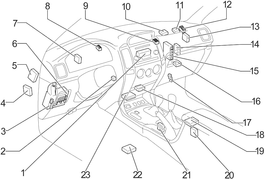
- A/C Control Assembly (Automatic A/C (without Navigation System))
- Transponder Key Amplifier
- Fuse Box
- Suspension Control ECU
- Skid Control ECU (with VSC A/T)
- Body ECU
- Theft Deterrent ECU
- J/B №1
- J/B №2
- Viscous Heater Amplifier
- Transponder Key Computer
- J/B №3
- Skid Control ECU (with VSC M/T)
- A/C ECU (Automatic A/C (with Navigation System))
A/C Amplifier (Manual A/C) - Engine and ECT ECU (A/T)
Engine ECU (M/T) - Center Diff. Lock ECU
Rear Diff. Lock Control ECU - Relay Box
- Gateway ECU
- Navigation ECU
- Cool Box Amplifier
- Shift Lock Control ECU
- Stereo Component Amplifier
- Airbag Sensor Assembly
Right-hand drive
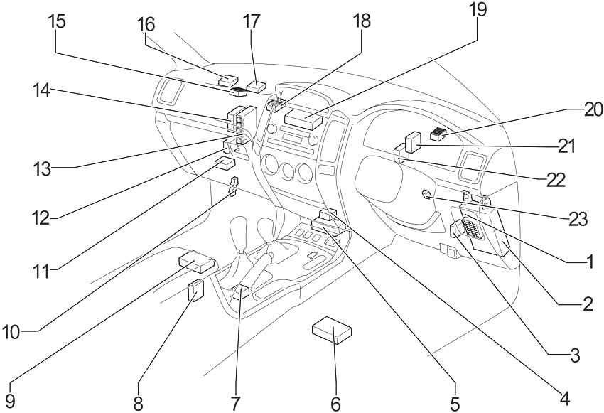
- Body ECU
- Fuse Box
- Skid Control ECU (with VSC)
- Gateway ECU
- Airbag Sensor Assembly
- Navigation ECU
- Shift Lock Control ECU
- Cool Box Amplifier
- Stereo Component Amplifier
- Relay Box
- Center Diff. Lock ECU
Rear Diff. Lock Control ECU - Suspension Control ECU
- Engine and ECT ECU (A/T)
Engine ECU (M/T) - A/C ECU (Automatic A/C (with Navigation System))
A/C Amplifier (Manual A/C) - J/B №3
- Transponder Key Computer
- Viscous Heater Amplifier
- J/B №2
- A/C Control Assembly (Automatic A/C (without Navigation System))
- J/B №
- Theft Deterrent ECU
- Double Door Lock Control Relay
- Transponder Key Amplifier
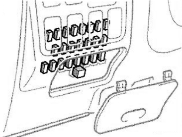
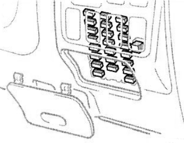
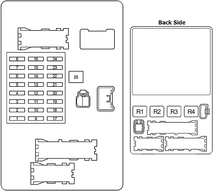
Passenger Compartment Fuse Box Diagram
The fuse panel is located behind the cover on the driver’s side of the dashboard.
Left-hand drive
Right-hand drive
Advertisements
| № | Fuse | A | Circuit |
|---|---|---|---|
| 1 | IGN | 10 | Electronically controlled fuel pump, multiport fuel injection system/sequential multiport fuel injection system, anti−lock brake system, active traction control system, vehicle stability control system |
| 2 | SRS | 10 | SRS airbags |
| 3 | GAUGE | 7.5 | Gauges and meters |
| 4 | ST2 | 7.5 | Multiport fuel injection system/sequential multiport fuel injection system |
| 5 | FR WIP−WSH | 30 | Windshield wipers and washer |
| 6 | TEMS | 20 | Toyota electronic modulated suspension |
| 7 | DIFF | 20 | Rear differential lock system, center differential lock system |
| 8 | RR WIP | 15 | Rear window wiper |
| 9 | - | - | - |
| 10 | D P/SEAT | 30 | LHD: Driver's power seat |
| P P/SEAT | 30 | RHD: Front passenger’s power seat | |
| 11 | P P/SEAT | 30 | LHD: Front passenger’s power seat |
| D P/SEAT | 30 | RHD: Driver's power seat | |
| 12 | PWR OUTLET | 15 | Power outlets |
| 13 | IG1 №2 | 10 | Air conditioning system, cool box |
| 14 | RR WSH | 15 | Rear window washer |
| 15 | ECU-IG | 10 | Shift lock control system, power windows, anti-lock brake system, active traction control system, vehicle stability control system, air conditioning system, electric moon roof, power outlets |
| 16 | IG1 | 10 | Anti-lock brake system, active traction control system, vehicle stability control system, air conditioning system, charging system, rear window defogger, back-up lights, turn signal lights, emergency flashers |
| 17 | STA | 7.5 | Electronically controlled fuel pump |
| 18 | P FR P/W | 20 | Front passenger’s power window |
| 19 | P RR P/W | 20 | LHD: Rear passenger’s power window |
| D RR P/W | 20 | RHD: Rear passenger’s power window | |
| 20 | D RR P/W | 20 | LHD: Rear passenger’s power window |
| P RR P/W | 20 | RHD: Rear passenger’s power window | |
| 21 | PANEL | 10 | Instrument panel lights |
| 22 | TAIL | 10 | Tail lights, license plate lights, parking lights |
| 23 | ACC | 7.5 | Electronically controlled automatic transmission system, power outlets, outside rear view mirrors, audio system |
| 24 | CIG | 10 | Cigarette lighter |
| 25 | POWER | 30 | Power windows, electric moon roof |
| R1 | Horn | ||
| R2 | Tail lights | ||
| R3 | Power relay | ||
| R4 | Accessory socket (ACC SKT) | ||
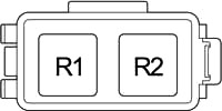
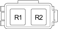
Relay Box
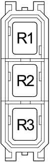
| № | Relay |
|---|---|
| R1 | Panel relay |
| R2 | Back-up lights (BK/UP LP) |
| R3 | Outside rear view mirror heaters (MIR HTR) |
Engine Compartment
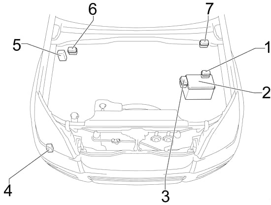
- Relay Box №1
- Fuse Box
- Relay Box №2
- Headlight Cleaner Relay
- Skid Control ECU with Actuator (without VSC)
- Relay Box №3 (LHD)
- Relay Box №3 (RHD)
Advertisements
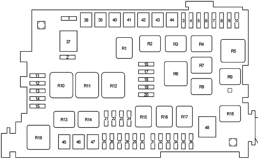
Engine Compartment Fuse Box Diagram
| № | Fuse | A | Circuit |
|---|---|---|---|
| 1 | SPARE | 10 | Spare fuse |
| 2 | SPARE | 15 | Spare fuse |
| 3 | CDS FAN | 20 | Electric cooling fan |
| 4 | RR A/C | 30 | Rear cooler system |
| 5 | MIR HEATER | 10 | Outside rear view mirror heaters |
| 6 | STOP | 10 | Stop lights, high mounted stop light, shift lock control system, anti−lock brake system, active traction control system, vehicle stability control system, rear height control air suspension |
| 7 | - | - | - |
| 8 | FR FOG | 15 | Front fog lights |
| 9 | VISCUS | 7.5 | Viscous heater |
| 10 | OBD | 7.5 | On-board diagnosis system |
| 11 | HEAD (LO RH) | 10 | Right-hand headlight (low beam) |
| 12 | HEAD (LO LH) | 10 | Left-hand headlight (low beam) |
| 13 | HEAD (HI RH) | 10 | Right-hand headlight (high beam) |
| 14 | HEAD (HI LH) | 10 | Left-hand headlight (high beam) |
| 15 | EFI №2 | 10 | 2O2 sensor and Air flow meter |
| 16 | HEATER №2 | 7.5 | Air conditioning system |
| 17 | DEFOG | 30 | Rear window defogger |
| 18 | AIRSUS №2 | 10 | Rear height control air suspension system |
| 19 | FUEL HEATER | 20 | Fuel heater |
| 20 | SEAT HEATER | 20 | Seat heater |
| 21 | DOME | 10 | Interior lights, personal lights, wireless remote control system, ignition switch light, door courtesy lights |
| 22 | RADIO №1 | 20 | Audio system |
| 23 | ECU−B | 10 | Anti−lock brake system, active traction control system, vehicle stability control system, air conditioning system, cool box, power windows |
| 24 | ECU−B №2 | 10 | Multiplex communication system |
| 25 | - | - | Short pin |
| 26 | ALT−S | 7.5 | Charging system |
| 27 | - | - | - |
| 28 | HORN | 10 | Horns |
| 29 | A/F HEATER | 15 | A/F sensor |
| F/PMP | 15 | 1KD−FTV: Fuel pump | |
| 30 | TRN−HAZ | 15 | Turn signal lights, emergency flashers |
| 31 | ETCS | 10 | Multiport fuel injection system/sequential multiport fuel injection system |
| 32 | EFl | 20 | Electronically controlled fuel pump, fuel pump, multiport fuel injection system/sequential multiport fuel injection system |
| 25 | 1KD−FTV: Electronically controlled fuel pump, fuel pump, multiport fuel injection system/sequential multiport fuel injection system | ||
| 33 | D FR P/W | 20 | Driver's power window |
| 34 | DR/LCK | 25 | Power door lock system |
| 35 | - | - | - |
| 36 | RADIO №2 | 30 | Audio system |
| 37 | ALT | 120 | without PTC: Defog relay, ignition relay, "HEATER”, "CDS FAN”, "AM1", "J/B", "VISCUS", "OBD", "MIR HEATER", "STOP", "FR FOG”, "AIRSUS”, "RR A/C” and "STOP” fuses |
| 140 | with PTC: Defog relay, ignition relay, "HEATER”, "CDS FAN”, "AM1", "J/B", "VISCUS", "OBD", "MIR HEATER", "STOP", "FR FOG”, "PTC-1", "PTC-2", "PTC-3", "AIRSUS”, "RR A/C” and "STOP” fuses | ||
| 38 | HEATER | 50 | Air conditioning system |
| 39 | AIRSUS | 50 | Rear height control air suspension |
| 40 | AM1 | 50 | All components in "ACC”, "CIG”, "IG1”, "IG1 №2”, "ECU−IG”, "FR WIP−WSH”, "RR WIP”, "RR WSH”, "DIFF”, "TEMS” and "STA” fuses |
| 41 | PTC-1 | 40 | Viscous heater |
| 42 | J/B | 50 | All components in "PWR OUTLET”, "P FR P/W”, "P RR P/W”, "D RR P/W”, "D P/SEAT”, "P P/SEAT”, "POWER”, "TAIL” and "PANEL” fuses |
| 43 | PTC-2 | 40 | Viscous heater |
| 44 | PTC-3 | 40 | Viscous heater |
| 45 | ABS MTR | 40 | Anti−lock brake system, active traction control system, vehicle stability control system |
| 46 | AM2 | 30 | Starter system, "IGN”, "GAUGE” and "SRS” fuses |
| 47 | ABS SOL | 30 | without the vehicle stability control system: Anti−lock brake system |
| 50 | with the vehicle stability control system: Anti−lock brake system, active traction control system, vehicle stability control system | ||
| 48 | GLOW | 80 | Engine glow system |
| R1 | Electric cooling fan (CDS FAN) | ||
| R2 | Accessory (ACC CUT) | ||
| R3 | Fog light | ||
| R4 | Starter (STA) | ||
| R5 | Ignition (IG) | ||
| R6 | Heater | ||
| R7 | Air conditioner compressor clutch (MG CLT) | ||
| R8 | - | ||
| R9 | Rear windshield defogger (DEFOG) | ||
| R10 | Anti−lock brake system (ABS MTR) | ||
| R11 | TRC MTR | ||
| R12 | Anti−lock brake system (ABS SOL) | ||
| R13 | Downhill Assist Control system (DAC) | ||
| R14 | Circuit opening Relay (C/OPN) or EDU | ||
| R15 | - | ||
| R16 | EFI | ||
| R17 | Air fuel ratio sensor (A/F HEATER) | ||
| R18 | Fuel pump | ||
| R19 | Headlight (HEAD) | ||
Relay Box №1
| № | Relay |
|---|---|
| R1 | Starter (STA) |
| R2 | Glow system (GLOW) |
Relay Box №2
| № | Relay |
|---|---|
| R1 | Air suspension (AIR SUS) |
| R2 | Dimmer (with Daytime Running Light) |
Relay Box №3
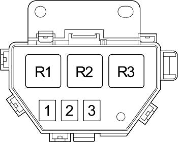
| № | Relay |
|---|---|
| R1 | PTC №1 |
| R2 | PTC №2 |
| R3 | PTC №3 |
Advertisements