
Advertisements
Fuse box diagram (fuse layout), location, and assignment of fuses and relays Toyota Land Cruiser 100 / J100 (2003, 2004, 2005, 2006, 2007).

Checking and Replacing Fuses
The fuses are designed to blow before the entire wiring harness is damaged. If any of the electrical components do not operate, a fuse may have blown. If this happens, check and replace the fuses as necessary.
- Turn the engine switch off and turn off all electrical accessories.
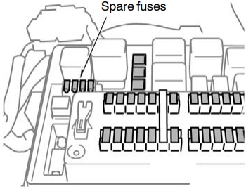
- Open the fuse box cover.
- See diagrams below for details about which fuse to check.
- Remove the fuse.
- Check if the fuse is blown – if the thin wire inside is broken, the fuse has blown.
- Replace the blown fuse with a new fuse of an appropriate amperage rating.
Notice
- Never use a fuse of a higher amperage rating than that indicated, or use any other object in place of a fuse, even as a temporary fix. This can cause extensive damage or even fire.
- Always use a genuine Toyota fuse or equivalent.
- Do not modify the fuses or fuse boxes.
- If the replaced fuse blows again, have the vehicle inspected by any authorized Toyota dealer or repairer, or another duly qualified and equipped professional.
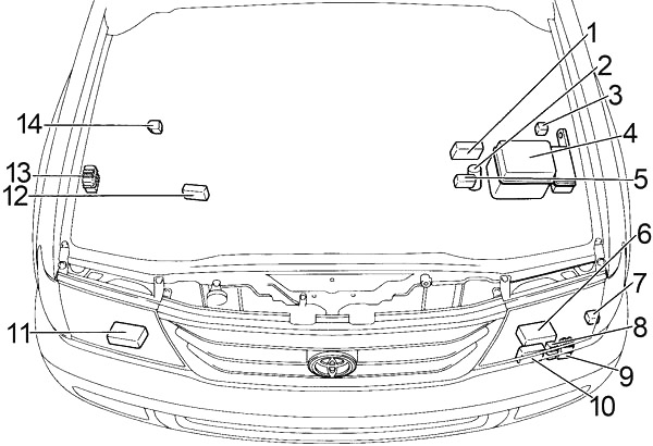
Passenger Compartment
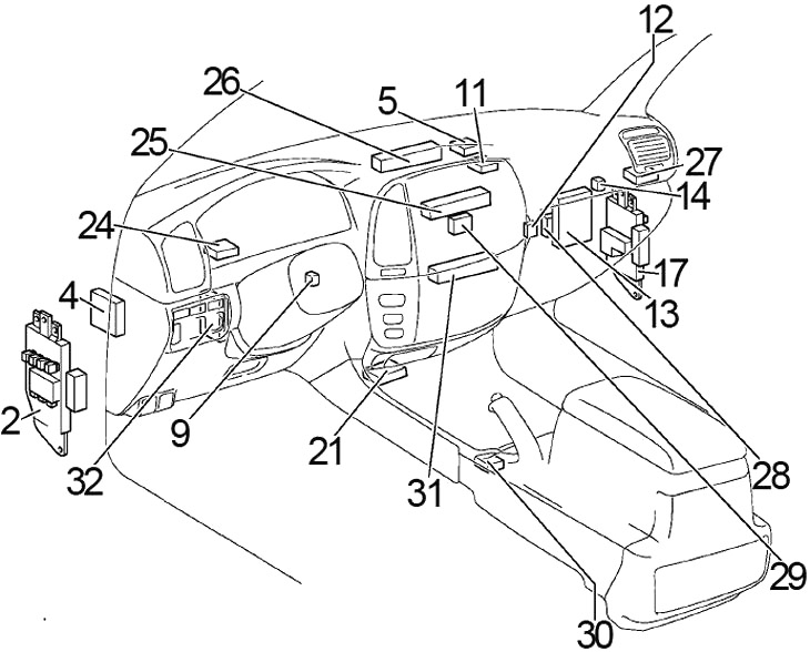
- Fuse Box/ Body ECU
- Tilt and Telescopic ECU
- Transponder Key Computer
- Transponder Key Amplifier
- Theft Deterrent ECU
- Auto Antenna Relay
- Engine and ECT ECU
- Center Differential Lock Control Relay
- Fuse Box
- Center Airbag Sensor Assembly
- A/C Control (with Navigation System)
- Junction Block
- Junction Block
- Junction Block
- Junction Block
- Gateway ECU
- Shift Lock Control ECU
- A/C Control (without Navigation System)
- ABS & BA & TRAC & VSC ECU
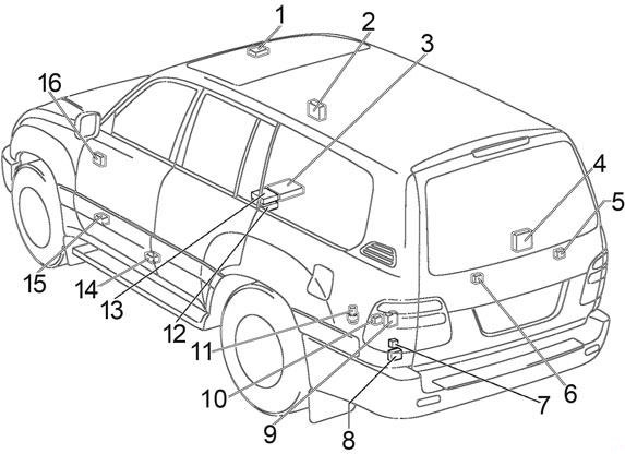
Liftgate Type
Swing Type
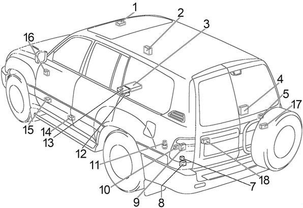
- Moon Roof Control ECU
- RHD: Remote Control Mirror ECU
- Stereo Component Amplifier
- A/C Amplifier
- Rear Cooler Relay
- Liftgate Type: Rear Wiper Relay
- Towing Hitch Relay
- Towing Converter Relay
- Fuel Pump Control ECU
- Fuel Pump Select Relay
- Sub Fuel Pump Forcing Driving Relay
- Television Camera ECU
- Navigation ECU
- Rear Heater Relay
- Control Valve Assembly
- LHD: Remote Control Mirror ECU
- Swing Type: Rear Wiper Relay RH
- Swing Type: Rear Wiper Relay LH
Advertisements
Left Passenger Compartment Fuse Box
The fuse panel is located behind the cover below the left side of the dashboard.
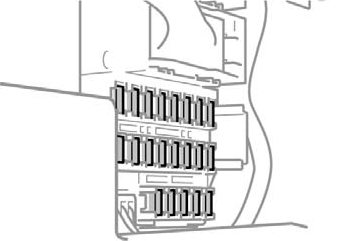
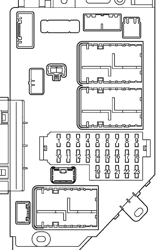
Back-side:
| № | Fuse | A | Circuit |
|---|---|---|---|
| 1 | PWR OUTLET | 15 | Power outlets |
| 2 | CIG | 15 | Cigarette lighter |
| 3 | ACC | 7.5 | Instrument panel light |
| 4 | AM1 | 7.5 | Multiport fuel injection system/Sequential multiport fuel injection system |
| 5 | DEFOG | 20 | Rear window defogger |
| 6 | AHC−B | 15 | Active height control suspension (AHC) |
| 7 | FUEL HTR | 20 | Fuel heater |
| 8 | POWER HTR | 7.5 | Power heater |
| 9 | AHC−IG | 20 | Active height control suspension (AHC) |
| 10 | EFI №2 | 10 | Emission control system |
| ECD №2 | 10 | Emission control system | |
| 11 | GAUGE1 | 10 | Gauges and meters |
| 12 | ECU−IG1 | 10 | Multiport fuel injection system/Sequential multiport fuel injection system |
| 13 | ECU−B1 | 10 | Navigation system |
| 14 | DBL LOCK | 15 | Double lock system |
| 15 | BATT CHARGE | 30 | Trailer charging system |
| 16 | A/C | 15 | Air conditioning system |
| 17 | STOP | 15 | Stop lights |
| 18 | OBD−2 | 7.5 | On−board diagnosis system |
| 19 | IDEL UP | 7.5 | Idle−up system |
| 20 | LH SEAT | 30 | Power seat system |
| 21 | DOOR | 25 | Power door lock system, Power windows |
| 22 | SUN ROOF | 25 | Electronic moon roof |
| 23 | RR WIPER | 15 | Rear wiper system |
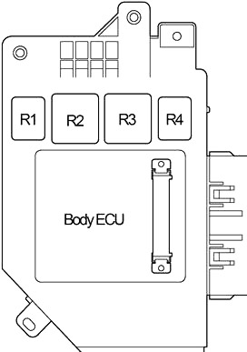
| R1 | Rear windshield defogger (DEFOG) | ||
| R2 | Ignition (IG1 №2) | ||
| R3 | Ignition (ACC) | ||
| R4 | Interior lights (DOME) | ||
Right Passenger Compartment Fuse Box
The fuse panel is located behind the cover below the right side of the dashboard.

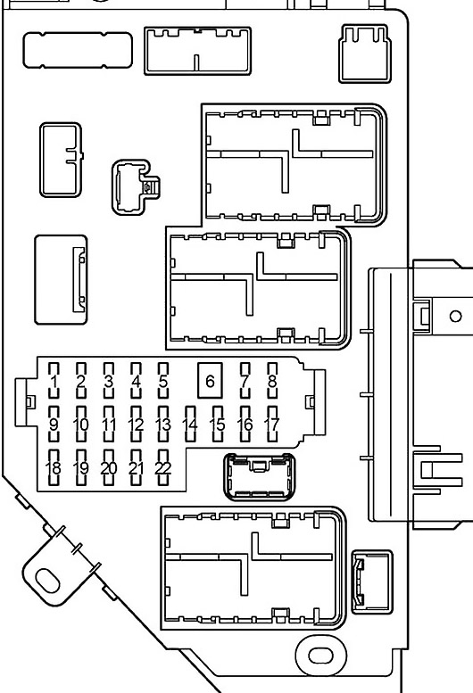
Back-side:
Advertisements
| № | Fuse | A | Circuit |
|---|---|---|---|
| 1 | ECU−B2 | 10 | Power door lock system, Power window |
| 2 | DIFF | 20 | Four−wheel drive system |
| 3 | WASHER | 15 | Windshield washer |
| 4 | RADIO | 10 | Audio system |
| 5 | DOME | 10 | Interior lights |
| 6 | VGRS | 40 | Variable gear ratio steering system |
| 7 | P/W (FL) | 20 | Power window |
| 8 | P/W (RL) | 20 | Power window |
| 9 | WIPER | 25 | Windshield wiper |
| 10 | ECU−IG2 | 10 | Rear air conditioning system |
| 11 | SEAT HTR | 15 | Seat heater |
| 12 | GAUGE2 | 10 | Back−up lights |
| 13 | MET | 7.5 | Gauges and meters |
| 14 | ING | 7.5 | Multiport fuel injection system/Sequential multiport fuel injection system |
| 15 | SECURITY | 7.5 | Theft deterrent system |
| 16 | P/W (RR) | 20 | Power window |
| 17 | P/W (FR) | 20 | Power window |
| 18 | BATT CHARGE | 30 | Trailer charging system |
| 19 | - | - | - |
| 20 | TIL&TEL | 20 | Tilt and telescopic steering |
| 21 | RR A/C | 30 | Rear air conditioning system |
| 22 | RH SEAT | 30 | Power seat system |
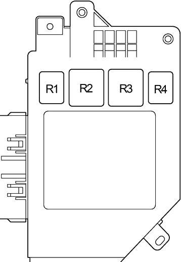
| R1 | Stop lights (STOP LP) | ||
| R2 | - | ||
| R3 | Ignition (IG1 №3) | ||
| R4 | Accessory (ACC CUT) | ||
Engine Compartment
- Injector Driver (EDU)
- Winch Main Relay
- Glow Plug Relay
- Fuse Box
- Fusible Link Block
- Headlight Control ECU LH
- Viscous Heater Relay
- Water Temperature Cut Relay
- A/C Condenser Fan Relay
- Headlight Cleaner Control Relay
- Headlight Control ECU RH
- Fusible Link Block (Cold Area)
- Daytime Running Light Relay No.3
- Intake Heater Relay
Advertisements
Engine Compartment Fuse Box Diagram
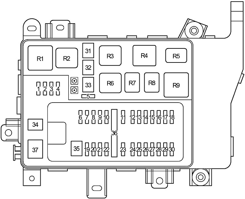
| № | Fuse | A | Circuit |
|---|---|---|---|
| 1 | - | - | - |
| 2 | - | - | - |
| 3 | - | - | - |
| 4 | - | - | - |
| 5 | ST1 | 7.5 | 2003-2005: Mutiport fuel injection system/Sequential multiport fuel injection |
| WIP−S | 7.5 | 2006-2007: - | |
| 6 | TOWING | 30 | Trailer lights |
| 7 | MIR HTR | 15 | Outside rear view mirror defogger |
| 8 | RR HTR | 10 | Rear air conditioning system |
| 9 | HAZ−TRN | 15 | Emergency flashers, Turn signal lights |
| 10 | ALT−S | 7.5 | Charging system |
| 11 | NV−IR | 20 | |
| 12 | FR FOG | 15 | Fog lights |
| 13 | TOWING BRK | 30 | Trailer lights |
| 14 | HEAD CLNER | 20 | Headlight cleaner |
| 15 | FR−IG | 10 | Charging system |
| 16 | PANEL | 7.5 | Instrument panel light |
| 17 | TOWING TAIL | 30 | Trailer lights |
| 18 | TAIL | 15 | Parking lights, Tail lights |
| 19 | BAT | 30 | "ECU−B2” fuse |
| 20 | TEL | 7.5 | |
| 21 | AMP | 30 | Audio system |
| 22 | EFI №1 | 25 | Mutiport fuel injection system/Sequential multiport fuel injection |
| ECD №1 | 25 | Mutiport fuel injection system/Sequential multiport fuel injection | |
| 23 | AM2 | 15 | "IGN” fuse |
| 24 | ETCS | 10 | Mutiport fuel injection system/Sequential multiport fuel injection |
| 25 | HORN | 10 | Horns |
| 26 | - | - | - |
| 27 | HEAD (RH−LWR) | 10 | Right−hand headlight (low beam) |
| 28 | HEAD (LH−LWR) | 10 | Left−hand headlight (low beam) |
| 29 | HEAD (RH−UPR) | 20 | Right−hand headlight (high beam) |
| 30 | HEAD (LH−UPR) | 20 | Left−hand headlight (high beam) |
| 31 | ABS №2 | 40 | Anti−lock brake system |
| 32 | ABS №1 | 50 | Anti−lock brake system |
| 33 | AHC | 50 | Active height control suspension (AHC) |
| 34 | STARTER | 30 | Starting system |
| 35 | SHORT PIN A | - | "BAT", "AMP" fuses |
| 36 | SHORT PIN B | - | "HAZ-TRN", "ALT-S" fuses |
| 37 | GLOW | 80 | Engine glow system |
| R1 | Heater (HTR) | ||
| R2 | Anti−lock brake system (ABS MTR1) | ||
| R3 | Anti−lock brake system (ABS MTR2) | ||
| R4 | Anti−lock brake system (ABS SOL) | ||
| R5 | Engine control unit (EFI) | ||
| Engine control unit (ECD) | |||
| R6 | Active height control suspension | ||
| R7 | Circuit opening (Fuel pump (C/OPN)) | ||
| R8 | Fuel pump (F/PUMP) | ||
| R9 | Starter | ||
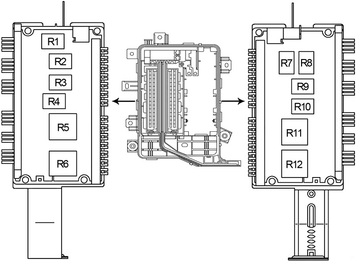
| № | Relay |
|---|---|
| R1 | Cooling system |
| R2 | Air conditioner compressor clutch (MG CLT) |
| R3 | Electric cooling fan (CDS FAN) |
| R4 | Horn |
| R5 | Headlight (HEAD) |
| R6 | High beam (HEAD HI) |
| R7 | Outside rear view mirror defogger (MIR HTR) |
| R8 | Rear heater (RR HTR) |
| R9 | Instrument panel (PANEL) |
| R10 | Front fog light (FR FOG) |
| R11 | Ignition (IG №1) |
| R12 | Tail lights (TAIL) |
Fusible Link Block
It is on the battery positive terminal.
| № | Fuse | A | Circuit |
|---|---|---|---|
| 1 | HTR | 50 | Air conditioning system |
| 2 | J/B №1 | 120 | "IG1 №1" relay, "TAIL" relay, "MIR HTR", "RR HTR", "TOWING BRK", "TOWING", "FR FOG" fuses |
| 3 | J/B №2 | 120 | "IG1 №2" relay, "ACC" relay, "DEFOG", "AM1", "LH SEAT", "STOP", "ECU-B1", "SUN ROOF", "OBD-2", "DOOR" fuses |
| 4 | J/B №3 | 120 | "IG1 №3" relay, "SECURITY", "TIL & TEL", "RH SEAT", "RR A/C", "P/W (RR)", "P/W (RL)", "P/W (FR)", "P/W (FL)" fuses |
| 5 | MAIN | 100 | "HEAD HI" Relay, "HEAD" Relay, "ABS №1", "ABS №2", "SHORT PIN A", "EFI OR ECD №1", "SHORT PIN B", "AM2", "STARTER", "HORN", "ECTS" fuses |
| 6 | ALT | 140 | "J/B №1", "J/B №2", "J/B №3", "HTR" fuses |
Advertisements