
Advertisements
Fuse box diagram (fuse layout), location, and assignment of fuses and relays Toyota Hilux (AN10, AN20, AN30) (2004, 2005, 2006, 2007, 2008, 2009, 2010, 2011, 2012, 2013, 2014, 2015).

Checking and Replacing Fuses
The fuses are designed to blow before the entire wiring harness is damaged. If any of the electrical components do not operate, a fuse may have blown. If this happens, check and replace the fuses as necessary.
- Turn the engine switch off (with a smart key system – turn the “ENGINE START STOP” switch off) and turn off all electrical accessories.
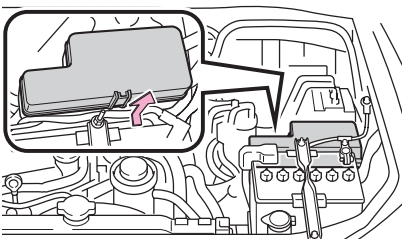
- Open the fuse box cover.
- See diagrams below for details about which fuse to check.
- Remove the fuse.
- Check if the fuse is blown – if the thin wire inside is broken, the fuse has blown.
- Replace the blown fuse with a new fuse of an appropriate amperage rating.
Notice
- Never use a fuse of a higher amperage rating than that indicated, or use any other object in place of a fuse, even as a temporary fix. This can cause extensive damage or even fire.
- Always use a genuine Toyota fuse or equivalent.
- Do not modify the fuses or fuse boxes.
- If the replaced fuse blows again, have the vehicle inspected by any authorized Toyota dealer or repairer, or another duly qualified and equipped professional.
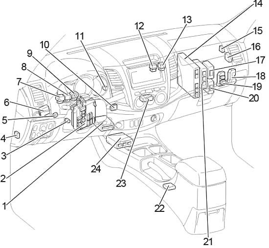
Passenger Compartment
Left-hand drive
Right-hand drive
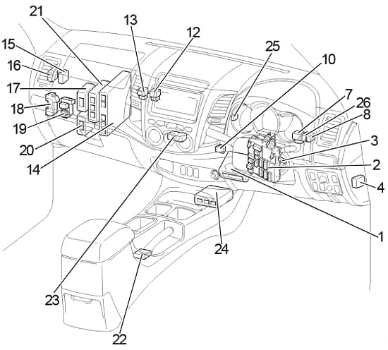
- A/C Amplifier (with Air Conditioner)
Viscous Heater Amplifier (without Air Conditioner) - Fuse Box / Integration Relay
- Transponder Key Amplifier
- 4WD Control ECU (Rear Differential Lock)
- LHD: Tail Lamp Relay (Aug. 2006 – Jun. 2011)
- LHD: Daytime Running Light Relay
- Turn Signal Flasher
- Magnet Clutch Relay
- LHD: Tail Lamp Relay (Before Aug. 2006)
LHD: Rear Fog Lamp Relay (From Aug. 2006) - Junction Connector
- LHD: Tail Lamp Relay (From Jun. 2011)
- PTC Heater Relay (№2)
- PTC Heater Relay (№1)
- Engine ECU
- Door Control Receiver
- Theft Warning ECU
- 4WD Control ECU
- Relay Box (From Jun. 2011)
- Relay Box (Before Jun. 2011)
- Turbo Motor Driver
- Transmission Control ECU
- Shift Lock Control ECU
- A/C Control Assembly
- Airbag Sensor Assembly Center
- RHD: Tail Lamp Relay
- RHD: Rear Fog Lamp Relay
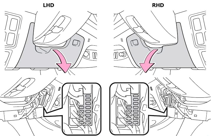
Passenger Compartment Fuse Box Diagram
The fuse panel is located on the driver’s side of the dashboard. Remove the bottom dashboard to access fuses.
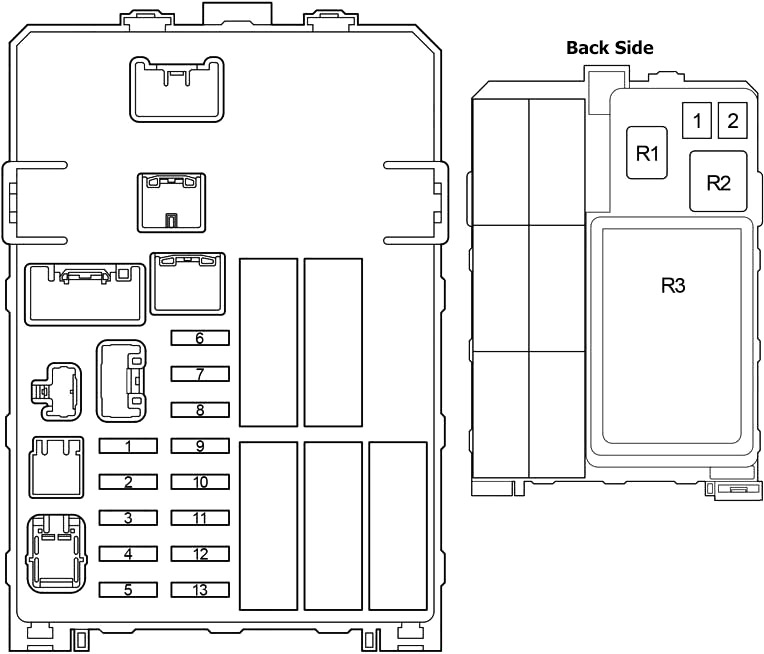
| № | Fuse | A | Circuit |
|---|---|---|---|
| 1 | INJ | 15 | Multiport fuel injection system/sequential multiport fuel injection system |
| 2 | OBD | 7.5 | On-board diagnosis system |
| 3 | STOP | 10 | Stop lights, high mounted stoplight, multiport fuel injection system/sequential multiport fuel injection system, ABS, TRC, VSC and shift lock control system |
| 4 | TAIL | 10 | Instrument panel light, front fog lights, headlight beam level control system, front position lights, tail lights, license plate lights, multiport fuel injection system/sequential multiport fuel injection system, multi-information display, daytime running light system and automatic headlight system |
| 5 | PWR OUT | 15 | Power outlet |
| 6 | ST | 7.5 | Starting system, gauges and meters and multiport fuel injection system/sequential multiport fuel injection system |
| 7 | A/C | 10 | Air conditioning system |
| 8 | MET | 7.5 | Gauges and meters and DPF system |
| 9 | CIG | 15 | Cigarette lighter |
| 10 | ACC | 7.5 | Audio system, power outlet, clock, power rear view mirror control system, shift lock control system and multi-information display |
| 11 | IGN | 7.5 | Multiport fuel injection system/sequential multiport fuel injection system, SRS airbags and fuel pump |
| 12 | WIP | 20 | Windshield wiper and washer |
| 13 | ECU-IG & GAUGE | 10 | Air conditioning system, charging system, rear differential lock system, ABS, TRC, VSC, emergency flashers, turn signal lights, back-up lights, multiport fuel injection system/sequential multiport fuel injection system, shift lock control system, rear window defogger, headlights, door courtesy switches, power door lock system, wireless remote control system, steering sensor, daytime running light system, cruise control, headlight cleaners, seat heaters, outside rear view mirror defoggers, multi-information display and passenger’s seat belt reminder light |
| 1 | AM1 | 40 | Rear differential lock system, ABS, TRC, VSC, "ACC", "CIG", "ECU-IG & GAUGE", and "WIP" fuses |
| 2 | IG1 | 40 | "PWR", "S-HTR", "4WD", "DOOR", "DEF" and "MIR HTR" fuses |
| R1 | Power outlet (PWR OUT) | ||
| R2 | Heater (HTR) | ||
| R3 | Integration relay | ||
Advertisements
Additional Fuse Box
Open the glove box. Press the glove box on both sides to disconnect the clamps.
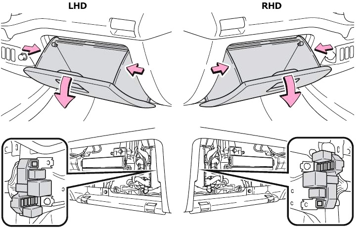
Diagram (Before Jun. 2011)
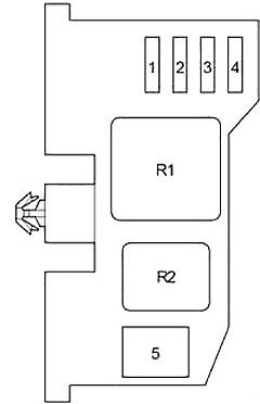
| № | Fuse | A | Circuit |
|---|---|---|---|
| 1 | DOOR | 25 | Power door lock system and power windows |
| 2 | DEF | 20 | Rear window defogger and multiport fuel injection system/sequential multiport fuel injection system |
| 3 | S-HTR | 15 | Seat heaters |
| 4 | 4WD | 20 | Rear differential lock system, ABS, TRC and VSC |
| 5 | PWR | 30 | Power windows |
| R1 | Ignition (IG1) | ||
| R2 | Rear window defogger (DEF) | ||
Diagram (From Jun. 2011)
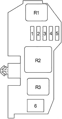
| № | Fuse | A | Circuit |
|---|---|---|---|
| 1 | MIR HTR | 15 | Before Nov. 2011: Outside rear view mirror defoggers |
| DOOR | 25 | From Nov. 2011: Power door lock system and power windows | |
| 2 | DOOR | 25 | Before Nov. 2011: Power door lock system and power windows |
| DEF | 20 | From Nov. 2011: Rear window defogger and multiport fuel injection system/sequential multiport fuel injection system | |
| 3 | DEF | 20 | Before Nov. 2011: Rear window defogger and multiport fuel injection system/sequential multiport fuel injection system |
| S-HTR | 15 | From Nov. 2011: Seat heaters | |
| 4 | S-HTR | 15 | Before Nov. 2011: Seat heaters |
| 4WD | 20 | From Nov. 2011: Rear differential lock system, ABS, TRC and VSC | |
| 5 | 4WD | 20 | Before Nov. 2011: Rear differential lock system, ABS, TRC and VSC |
| MIR HTR | 15 | From Nov. 2011: Outside rear view mirror defoggers | |
| R1 | Outside rear view mirror defoggers (MIR HTR) | ||
| R2 | Ignition (IG1) | ||
| R3 | Rear window defogger (DEF) | ||
Advertisements
Engine Compartment
Left-hand drive
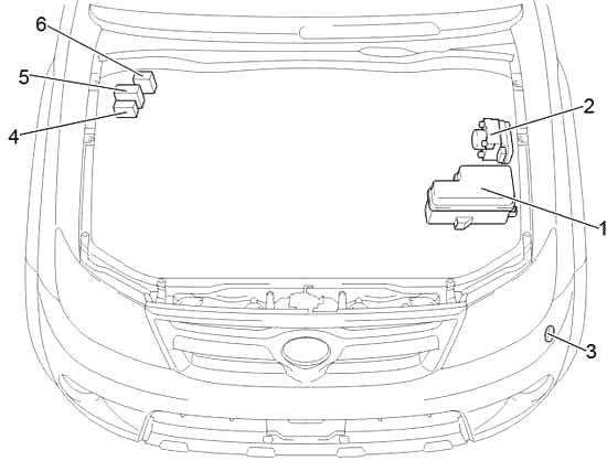
Right-hand drive
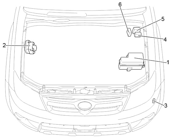
- Fuse Box
- Skid Control ECU with Actuator
- Headlight Cleaner Control Relay
- Glow Plug Controller
- 2TR-FE: Air Injection Control Driver
RHD: 1KD-FTV and 2KD-FTV (without DPF): Injector Driver (EDU)
LHD: 1KD-FTV and 2KD-FTV (with DPF): Injector Driver (EDU) - RHD: 1KD-FTV and 2KD-FTV (with DPF): Injector Driver (EDU)
LHD: 1KD-FTV and 2KD-FTV (without DPF): Injector Driver (EDU)
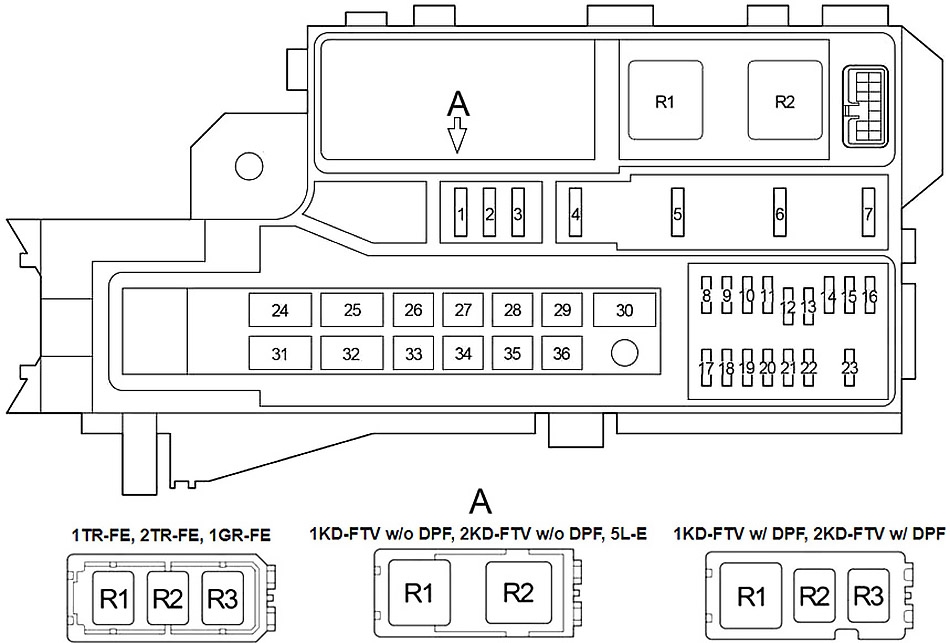
Engine Compartment Fuse Box Diagram
| № | Fuse | A | Circuit |
|---|---|---|---|
| 1 | - | 25 | Spare fuse |
| 2 | - | 15 | Spare fuse |
| 3 | - | 10 | Spare fuse |
| 4 | FOG | 7.5 | Europe, Morocco: |
| From Aug. 2012 - Aug. 2013: Front fog lights | |||
| From Aug. 2013: Front fog lights | |||
| 15 | Before Aug. 2013: Front fog lights | ||
| Except Europe, Morocco: | |||
| From Aug. 2012 - Aug. 2013: Front fog lights | |||
| 5 | HORN | 10 | Horn |
| 6 | EFI | 25 | Multiport fuel injection system/sequential multiport fuel injection system |
| 7 | - | - | - |
| 8 | H-LP RL | 20 | Before Jun. 2011: Right-hand headlight (Low) |
| 15 | From Jun. 2011: Right-hand headlight (Low) | ||
| 9 | H-LP LL | 20 | Before Jun. 2011: Left-hand headlight (Low) |
| 15 | From Jun. 2011: Left-hand headlight (Low) | ||
| 10 | H-LP RH | 20 | Before Jun. 2011: Right-hand headlight (High) and right-hand headlight (Low) |
| 15 | From Jun. 2011: Right-hand headlight (High) and right-hand headlight (Low) | ||
| 11 | H-LP LH | 20 | Before Jun. 2011: Left-hand headlight (High) and left-hand headlight (Low) |
| 15 | From Jun. 2011: Left-hand headlight (High) and left-hand headlight (Low) | ||
| 12 | EFI №2 | 10 | Multiport fuel injection system/sequential multiport fuel injection system |
| 13 | ECU-IG №2 | 10 | Multiport fuel injection system/ sequential multiport fuel injection system |
| 14 | ECU-B | 7.5 | Before Aug. 2008: Door courtesy switches, power door lock system, wireless remote control system, steering sensor and headlights |
| 10 | From Aug. 2008: Door courtesy switches, power door lock system, wireless remote control system, steering sensor and headlights | ||
| 15 | RAD | 15 | Before Aug. 2013: Audio system |
| 20 | From Aug. 2013: Audio system | ||
| 16 | DOME | 7.5 | Interior lights, engine switch light, personal light, gauges and meters, clock, multi-information display, wireless remote control system, daytime running light system and fog light |
| 17 | A/F | 20 | Emission control system |
| 18 | ETCS | 10 | Multiport fuel injection system/ sequential multiport fuel injection system, electric throttle control system |
| 19 | ALT-S | 7.5 | Charging system |
| 20 | TURN-HAZ | 15 | Emergency flashers and turn signal lights |
| 21 | - | - | - |
| 22 | ECU-B №2 | 7.5 | Air conditioning system |
| 23 | DCC | 30 | "ECU-B", "DOME" and "RAD" fuses |
| 24 | PTC №1 | 50 | Power heater |
| 25 | H-LP CLN | 30 | Before Jun. 2011: Headlight cleaners |
| PWR SEAT | 30 | Power seat | |
| 26 | PTC №2 | 50 | Europe: |
| From Aug. 2010 - Jun. 2011 (without Automatic A/C): Power heater | |||
| From Jun. 2011: Power heater | |||
| 30 | Europe: | ||
| Before Jun. 2011 (with Automatic A/C): Power heater | |||
| Before Aug. 2010 (without Automatic A/C): Power heater | |||
| Australia: Power heater | |||
| 27 | ABS №1 | 40 | Before Aug. 2008: ABS, TRC and VSC |
| H-LP CLN | 40 | From Jun. 2011: Headlight cleaners | |
| 28 | FR HTR | 40 | Before Aug. 2009: Air conditioning system, "A/C" fuse |
| 50 | From Aug. 2009: Air conditioning system, "A/C" fuse | ||
| 29 | ABS №2 | 30 | ABS, TRC and VSC |
| 30 | ABS №1 | 40 | From Aug. 2008: ABS, TRC and VSC |
| 31 | ALT | 100 | Charging system, "PWR SEAT", "HLP CLN", "FR HTR", "AM1", "IG1", "PTC №1", "PTC №2", "PWR OUT", "STOP", "TAIL" and "OBD" fuses |
| 32 | GLOW | 80 | Engine glow system |
| 33 | BATT P/I | 50 | "FOG", "HORN" and "EFI" fuses |
| 34 | AM2 | 30 | Engine starter, "ST", "IGN", "INJ" and "MET" fuses |
| 35 | MAIN | 40 | "H-LP RH", "H-LP LH", "H-LP RL" and "H-LP LL" fuses |
| 36 | A/PUMP | 50 | Multiport fuel injection system/sequential multiport fuel injection system |
| R1 | Dimmer (DIM) | ||
| R2 | Headlight (H-LP) | ||
| R1 | Starter (ST) | ||
| R2 | 1TR-FE, 2TR-FE, 1GR-FE: Air fuel ratio sensor (A/F) | ||
| 1KD-FTV w/o DPF, 2KD-FTV w/o DPF, 5L-E: Engine glow system (GLOW) | |||
| 1KD-FTV w/ DPF, 2KD-FTV w/ DPF: Air fuel ratio sensor (A/F) | |||
| R3 | 1TR-FE, 2TR-FE, 1GR-FE: Fuel pump (F/PMP) | ||
| 1KD-FTV w/ DPF, 2KD-FTV w/ DPF: - | |||
Advertisements