
Advertisements
Fuse box diagram (fuse layout), location, and assignment of fuses and relays Toyota Hilux (N140, N150, N160, N170) (1997, 1998, 1999, 2000, 2001, 2002, 2003, 2004, 2005).

Checking and Replacing Fuses
The fuses are designed to blow before the entire wiring harness is damaged. If any of the electrical components do not operate, a fuse may have blown. If this happens, check and replace the fuses as necessary.
- Turn the engine switch off and turn off all electrical accessories.
- Open the fuse box cover.
- See diagrams below for details about which fuse to check.
- Remove the fuse.
- Check if the fuse is blown – if the thin wire inside is broken, the fuse has blown.
- Replace the blown fuse with a new fuse of an appropriate amperage rating.
Notice
- Never use a fuse of a higher amperage rating than that indicated, or use any other object in place of a fuse, even as a temporary fix. This can cause extensive damage or even fire.
- Always use a genuine Toyota fuse or equivalent.
- Do not modify the fuses or fuse boxes.
- If the replaced fuse blows again, have the vehicle inspected by any authorized Toyota dealer or repairer, or another duly qualified and equipped professional.
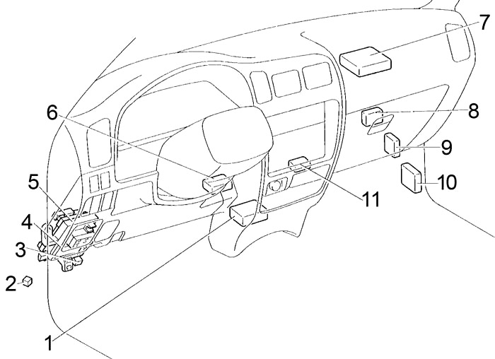
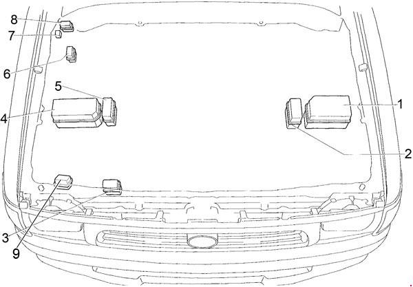
Passenger Compartment
Left-hand drive
Right-hand drive
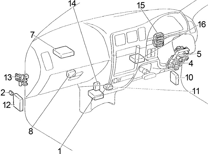
- Airbag Sensor Assembly
- ADD Control Relay
- LHD: Circuit Opening Relay (Fuel Pump)
- Integration Relay
- Fuse Box
- LHD: Daytime Running Light Relay
- Emission ECU (3RZ-F, 1RZ)
Pre-Heating Timer (Diesel)
LHD: Engine ECU (2RZ-FE)
RHD: Engine ECU (M/T) (3RZ-FE, 1RZ-E)
RHD: Engine and ECT ECU (A/T) (3RZ-FE, 1RZ-E) - A/C Amplifier
- LHD: Differential Lock ECU
- ABS ECU
- ABS Deceleration Sensor
- RHD:4WD Control ECU
- RHD: Relay Box (Circuit Opening Relay (Fuel Pump))
- RHD: Auto Antenna Control Relay
- RHD:
Australia: Junction Block
Except for Australia: Connector Holder - RHD: Dim-Dip Light Relay
Advertisements
Passenger Compartment Fuse Box Diagram
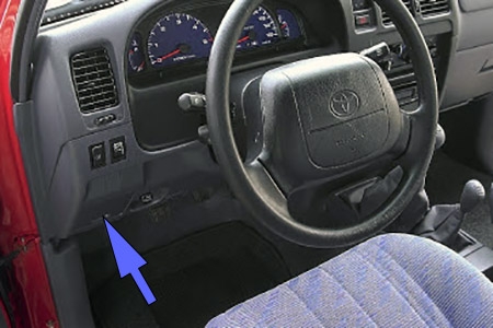
The fuse panel is located behind the cover on the driver’s side of the dashboard.
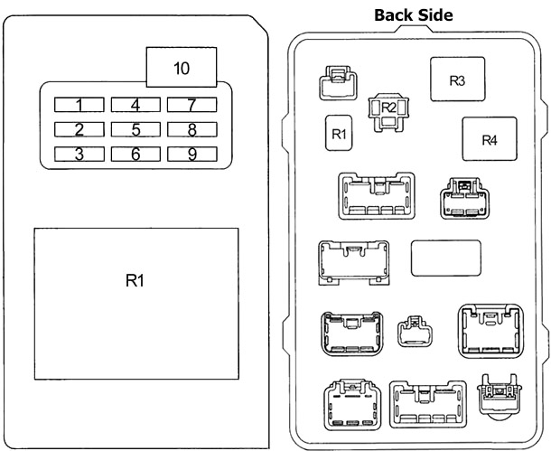
| № | Fuse | A | Circuit |
|---|---|---|---|
| 1 | SEAT-HTR | 20 | Seat heater |
| 2 | ACC | 15 | Cigarette lighter, clock, power rear view mirrors, back-up lights, shift lock system |
| 3 | ECU-B | 7.5 | Rear fog light, SRS airbag warning light, daytime running light system, cruise control system, anti-lock brake system |
| 4 | 4WD | 20 | A.D.D. control system, four-wheel drive control system, rear differential lock system |
| 5 | TURN | 10 | Turn signal lights, emergency flashers |
| 6 | GAUGE | 10 | Gauges and meters, back-up lights, cruise control system, power antenna, power door lock control system, electronically controlled automatic transmission system, starting system, charging system, heater control system |
| 7 | ECU-IG | 15 | Anti-lock brake system, shift lock system |
| 8 | WIPER | 20 | Windshield wipers and washer |
| 9 | IGN | 10 | Discharge warning light, SRS airbag system, multiport fuel injection system/sequential multiport fuel injection system |
| 10 | POWER | 30 | Power windows, power door lock control system |
| R1 | Integration relay | ||
| R1 | Horn | ||
| R2 | Turn signal flasher | ||
| R3 | Power relay | ||
| R4 | Defogger | ||
Relay Box (RHD)
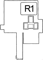
| № | Relay |
|---|---|
| R1 | Fuel Pump (Circuit Opening) |
Advertisements
Engine Compartment
- Fuse Box (Gasoline, LHD Diesel)
- Relay Box №1 (LHD Diesel)
- Relay Box №2
- Fuse Box (RHD Diesel)
- Relay Box №1 (RHD)
- Relay Box №3 (LHD)
- Headlight Cleaner Relay (LHD)
- Relay Box №3 (RHD)
- Relay Box №4 (Israel)
Engine Compartment Fuse Box Diagram (Type 1)
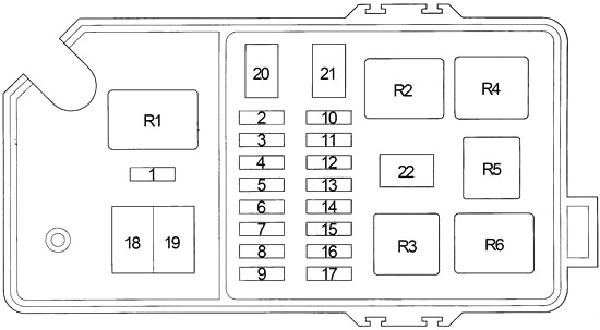
| № | Fuse | A | Circuit |
|---|---|---|---|
| 1 | - | - | - |
| 2 | DEFOG | 15 | Rear window defogger |
| 3 | STOP | 10 | Stop lights |
| 4 | ALT-S | 7.5 | Charging system |
| 5 | - | - | - |
| 6 | OBD | 7.5 | Petrol: On-board diagnosis system |
| AM2 | 20 | Diesel: Multiport fuel injection system/sequential multiport fuel injection system | |
| 7 | EFI | 15 | Multiport fuel injection system/sequential multiport fuel injection system |
| 8 | HORN | 15 | Horn, emergency flashers |
| 9 | DOME | 15 | Car audio system, power antenna, interior light, clock, ignition switch light, personal lights, door courtesy lights |
| AM2 | 20 | Multiport fuel injection system/sequential multiport fuel injection system | |
| 10 | TAIL | 10 | Tail lights, license plate lights, stop lights, air conditioning system, audio system, clock, cigarette lighter, instrument panel lights |
| 11 | - | - | - |
| 12 | A.C | 10 | Air conditioning system |
| 13 | STA | 7.5 | Multiport fuel injction system/sequential multiport fuel injection system, starting system, gauges and meters |
| 14 | HEAD (RH) | 10 | Right-hand headlight |
| 15 | HEAD (LH) | 10 | Left-hand headlight |
| 16 | HEAD (LO RH) | 10 | Right-hand headlight (low beam) |
| 17 | HEAD (LO LH) | 10 | Left-hand headlight (low beam) |
| 18 | ABS | 60 | Petrol: Anti-lock brake system |
| GLOW, ABS | 80 | Diesel: Engine glow system, anti-lock brake system | |
| 19 | ALT | 80 | 45A, 55A: "ABS”, "AM1”, "STA”, "ECU-B”, "POWER”, "RADIO”, "ACC”, "GAUGE”, "TURN”, "ECUI G”, "WIPER”, "4WD”, "HEATER”, "A.C”, "TAIL”, "PANEL”, "STOP” and "ALT-S” fuses |
| 100 | 70A: "ABS”, "AM1”, "STA”, "ECU-B”, "POWER”, "RADIO”, "ACC”, "GAUGE”, "TURN”, "ECUI G”, "WIPER”, "4WD”, "HEATER”, "A.C”, "TAIL”, "PANEL”, "STOP” and "ALT-S” fuses | ||
| 20 | HEATER | 50 | Air conditioning system |
| 21 | AM1 | 40 | Ignition switch, starter system, headlight cleaner relay, fuel heater, "ECU-B", "GAUGE" "POWER" |
| 22 | AM2 | 30 | Ignition switch |
| R1 | Dimmer | ||
| R2 | Tail lights (TAIL) | ||
| R3 | Headlights (HEAD) | ||
| R4 | Heater | ||
| R5 | Starter | ||
| R6 | (EFI) | ||
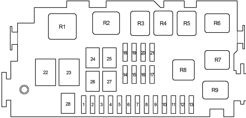
Engine Compartment Fuse Box Diagram (Type 2)
Advertisements
| № | Fuse | A | Designation |
|---|---|---|---|
| 1 | - | - | - |
| 2 | HEAD (RH) | 10 | Right−hand headlight |
| 3 | HEAD (LH) | 10 | Left−hand headlight |
| 4 | HEAD (RL) | 10 | Right−hand headlight (low beam) |
| 5 | HEAD (LL) | 10 | Left−hand headlight (low beam) |
| 6 | TAIL | 10 | Tail lights, licence plate lights |
| 7 | STA | 7.5 | Multiport fuel injction system/sequential multiport fuel injection system, starting system, gauges and meters |
| 8 | A/C | 10 | Air conditioning system |
| 9 | - | - | Not used |
| 10 | - | - | Not used |
| 11 | - | - | Not used |
| 12 | - | - | Not used |
| 13 | - | - | Not used |
| 14 | HORN | 15 | Horn |
| 15 | DOME | 15 | Audio system, interior light, clock, personal lights, door courtesy light, day time running light system, gauges and meters |
| 16 | OBD | 7.5 | On−board diagnosis system |
| 17 | EFI | 15 | 2RZ-FE, 3RZ-FE: Multiport fuel injection system/sequential multiport fuel injection system |
| ECD | 15 | 1KZ-TE, 5L-E: Multiport fuel injection system/sequential multiport fuel injection system | |
| AM2 | 20 | Diesel: Ignition system, multiport fuel injection system/sequential fuel injection system | |
| 18 | ALT−S | 7.5 | Charging system |
| 19 | DEFOG | 15 | Rear window defogger |
| 20 | STOP | 10 | Stop lights |
| 21 | - | - | Not used |
| 22 | ABS | 60 | Petrol: Anti-lock brake system |
| GLOW, ABS | 80 | Diesel: Engine glow system, anti-lock brake system | |
| 23 | ALT | 80 | 45A, 55A: "ABS”, "AM1”, "STA”, "ECU-B”, "POWER”, "RADIO”, "ACC”, "GAUGE”, "TURN”, "ECUI G”, "WIPER”, "4WD”, "HEATER”, "A.C”, "TAIL”, "PANEL”, "STOP” and "ALT-S” fuses |
| 100 | 70A: "ABS”, "AM1”, "STA”, "ECU-B”, "POWER”, "RADIO”, "ACC”, "GAUGE”, "TURN”, "ECUI G”, "WIPER”, "4WD”, "HEATER”, "A.C”, "TAIL”, "PANEL”, "STOP” and "ALT-S” fuses | ||
| 24 | HEATER | 50 | All components in "A.C” fuse |
| 25 | AM1 | 40 | Starting system |
| 26 | CDS FAN | 30 | Electric cooling fan |
| 27 | AM2 | 30 | Ignition system, multiport fuel injection system/sequential fuel injection system |
| 28 | - | - | - |
| R1 | Petrol: Starter | ||
| R2 | Heater | ||
| R3 | Electric cooling fan (CDS FAN) | ||
| R4 | Taillights (TAIL) | ||
| R5 | - | ||
| R6 | - | ||
| R7 | Engine control unit (EFI) | ||
| Engine control unit (ECD) | |||
| R8 | Headlight (HEAD) | ||
| R9 | Dimmer | ||
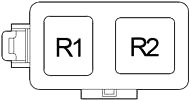
Relay Box №1
| № | Relay |
|---|---|
| R1 | Starter (ST) |
| R2 | Glow system (SUB GLW) |
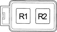
Relay Box №2
| № | Relay |
|---|---|
| R1 | Dim-Dip №3 |
| R2 | Dim-Dip №2 |
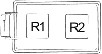
Relay Box №3
| № | Relay |
|---|---|
| R1 | Electric cooling fan (CDS FAN) |
| R2 | Electric cooling fan (CDS FAN №2) |
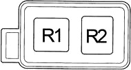
Relay Box №4
| № | Relay |
|---|---|
| R1 | Anti-lock brake system (ABS Motor) |
| R2 | Anti-lock brake system (ABS Solenoid) |
Advertisements