
Advertisements
Fuse box diagram (fuse layout), location, and assignment of fuses and relays Toyota HiAce (H200) (2004, 2005, 2006, 2007, 2008, 2009, 2010, 2011, 2012, 2013).

Checking and Replacing Fuses
The fuses are designed to blow before the entire wiring harness is damaged. If any of the electrical components do not operate, a fuse may have blown. If this happens, check and replace the fuses as necessary.
- Turn the engine switch off (with a smart key system – turn the “ENGINE START STOP” switch off) and turn off all electrical accessories.
- Open the fuse box cover.
- See diagrams below for details about which fuse to check.
- Remove the fuse.
- Check if the fuse is blown – if the thin wire inside is broken, the fuse has blown.
- Replace the blown fuse with a new fuse of an appropriate amperage rating.
Notice
- Never use a fuse of a higher amperage rating than that indicated, or use any other object in place of a fuse, even as a temporary fix. This can cause extensive damage or even fire.
- Always use a genuine Toyota fuse or equivalent.
- Do not modify the fuses or fuse boxes.
- If the replaced fuse blows again, have the vehicle inspected by any authorized Toyota dealer or repairer, or another duly qualified and equipped professional.
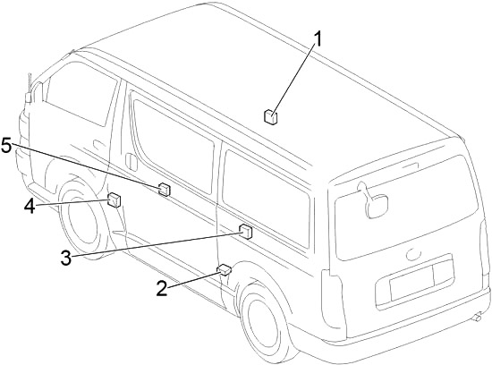
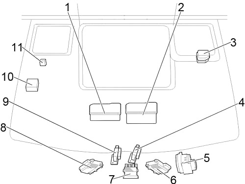
Passenger Compartment
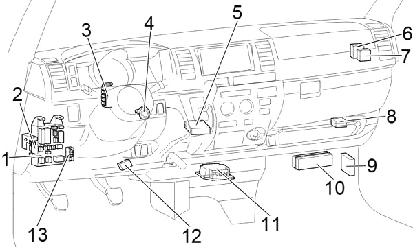
Left-hand drive
Right-hand drive
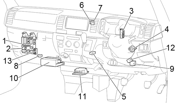
- Fuse Box
- Integration Relay
- Junction Block
- Transponder Key Amplifier
- Shift Lock Control ECU
- A/C Amplifier
- Clearance Warning ECU
- Additional Fuse Box
- Transmission Control ECU
- Relay Box
- Airbag Sensor Assembly Center
- Turbo Motor Driver
- Junction Connector (CAN)
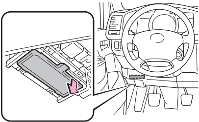
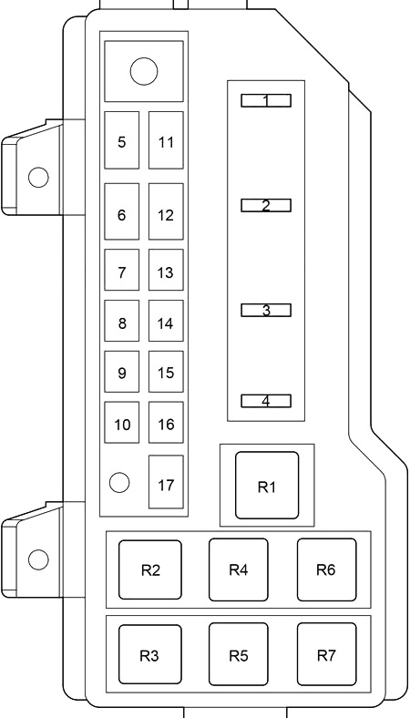
Passenger Compartment Fuse Box Diagram
The fuse panel is located under the left side of the dashboard. Remove the cover.
Left-hand drive
Right-hand drive
Advertisements
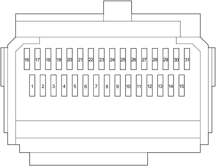
| № | Fuse | A | Circuit |
|---|---|---|---|
| 1 | - | - | - |
| 2 | ACCL INT LCK | 25 | - |
| 3 | WIP | 25 | Windshield wipers |
| 4 | RR WIP-WSH | 15 | Rear window wipers and washer |
| 5 | WSH | 20 | Window wipers and washer, rear window wipers and washer |
| 6 | ECU-IG | 7.5 | Air conditioning system, automatic transmission shift lock control system, anti-lock brake system, sliding door closer system, multiport fuel injection system/sequential multiport fuel injection system, multiplex communication system |
| 7 | GAUGE | 10 | Gauges and meters, rear turn signal lights, stop/tail lights, back-up lights, rear window defogger, electric cooling fans, charging system, air conditioning system, power windows |
| 8 | OBD | 7.5 | On-board diagnosis system |
| 9 | STOP | 10 | Rear turn signal lights, stop/tail lights, back-up lights, high-mounted stoplight |
| 10 | - | - | - |
| 11 | DOOR | 30 | Power windows, power door lock system |
| 12 | RR HTR | 15 | Air conditioning system |
| 13 | - | - | - |
| 14 | FR FOG | 15 | Before Apr. 2012: Front fog light |
| 10 | From Apr. 2012: Front fog light | ||
| 15 | AM1 | 30 | All components in "ACC”, and "CIG” fuses, starting system |
| 16 | TAIL | 10 | Front position lights, rear turn signal lights, stop/tail lights, back-up lights, license plate lights, clock, instrument panel light, multiport fuel injection system/sequential multiport fuel injection system |
| 17 | PANEL | 10 | Instrument panel light |
| 18 | A/C | 10 | Air conditioning system |
| 19 | - | - | - |
| 20 | - | - | - |
| 21 | - | - | - |
| 22 | - | - | - |
| 23 | CIG | 15 | Cigarette lighter |
| 24 | ACC | 7.5 | Power rear view mirror, automatic transmission shift lock control system |
| 25 | - | - | |
| 26 | ELS | 10 | Multiport fuel injection system/sequential multiport fuel injection system |
| 27 | AC100V | 15 | - |
| 28 | RR FOG | 15 | Rear turn signal lights, stop/tail lights, back-up lights |
| 29 | - | - | - |
| 30 | IGN | 15 | Multiport fuel injection system/sequential multiport fuel injection system, electronic throttle control system, SRS airbag system |
| 31 | MET IGN | 10 | Gauges and meters |
| № | Fuse | A | Circuit |
|---|---|---|---|
| 1 | POWER | 30 | Power windows |
| 2 | DEF | 30 | Rear window defogger |
| 3 | - | - | - |
| R1 | Ignition (IG1) | ||
| R2 | Heater (HTR) | ||
| R3 | Flasher | ||
Advertisements
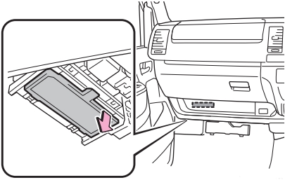
Relay Box
It is below the glove box. Push the tab and remove the cover.
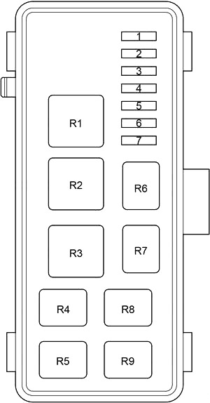
| № | Fuse | A | Circuit |
|---|---|---|---|
| 1 | HEAD LL | 15 | - |
| 2 | HEAD RL | 15 | - |
| 3 | HEAD LH | 15 | Left-hand headlight |
| 4 | HEAD RH | 15 | Right-hand headlight |
| 5 | ST | 7.5 | Starting system, multiport fuel injection system/sequential multiport fuel injection system, gauges and meters |
| 6 | A/C №3 | 7.5 | Air conditioning system |
| 7 | - | - | - |
| R1 | - | ||
| R2 | Headlight (HEAD) | ||
| R3 | - | ||
| R4 | Starter (ST) | ||
| R5 | (OSV) | ||
| R6 | - | ||
| R7 | Front fog light (FR FOG) | ||
| R8 | Air conditioner compressor clutch (MG CLT) | ||
| R9 | (INJ/IGN) | ||
- Door Control Relay (RH)
- Door Control Relay (Power Slide Door)
- Door Control Receiver
- Door Control Relay (LH)
- Door Opening Relay
Engine Compartment
- 1KD-FTV, 2KD-FTV, 5L-E: Fuse Box
- 1TR-FE, 2TR-FE: Fuse Box
- Additional Fuse Box
- Before Aug. 2010:Cooling Fan ECU №2
- Skid Control ECU with Actuator
- From Aug. 2010:Cooling Fan ECU №2
- Injector Driver (EDU)
- From Aug. 2010:Cooling Fan ECU №1
- Before Aug. 2010:Cooling Fan ECU №1
- Engine ECU
- 1TR-FE, 2TR-FE: Air Injection Control Driver
1KD-FTV, 2KD-FTV: Injection Driver (EDU)
Advertisements
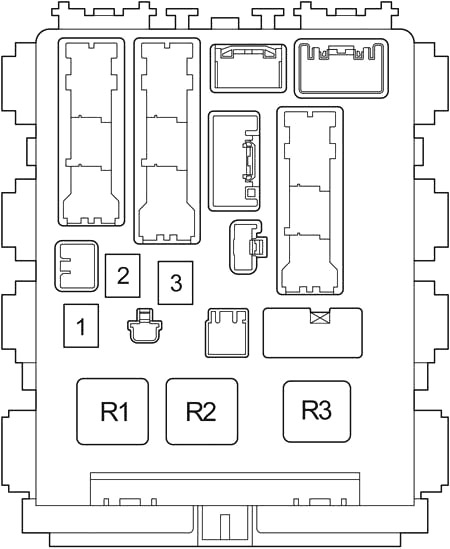
Engine Compartment Fuse Box Diagram
Push the tab and remove the cover.
| № | Fuse | A | Circuit |
|---|---|---|---|
| 1 | A/F | 15 | 1TR-FE, 2TR-FE: Multiport fuel injection system/sequential multiport fuel injection system |
| EDU | 25 | 1KD-FTV, 2KD-FTV, 5L-E: Multiport fuel injection system/sequential multiport fuel injection system | |
| 2 | HAZ-HORN | 15 | Horns, emergency flasher |
| 3 | EFI | 20 | 1TR-FE, 2TR-FE: Electronically controlled fuel pump, multiport fuel injection system/sequential multiport fuel injection system, electronic throttle control system |
| 25 | 1KD-FTV, 2KD-FTV, 5L-E: Electronically controlled fuel pump, multiport fuel injection system/sequential multiport fuel injection system, electronic throttle control system | ||
| 4 | - | - | - |
| 5 | ALT | 140 | All components in "MAIN3”, "FAN1”, "FAN2” and "GLOW” fuses |
| 150 | Refrigerator Van: All components in "MAIN3”, "FAN1”, "FAN2” and "GLOW” fuses | ||
| 6 | A/PUMP | 50 | 1TR-FE, 2TR-FE: Emission control system |
| GLOW | 80 | 1KD-FTV, 2KD-FTV, 5L-E: Engine glow system | |
| 7 | MAIN3 | 50 | All components in "A/F”, "HAZ-HORN” and "EFI” fuses |
| 8 | FAN2 | 50 | Electric cooling fans |
| 9 | FAN3 | 30 | 1KD-FTV, 2KD-FTV, 5L-E: Electric cooling fans |
| 10 | FAN1 | 50 | Electric cooling fans |
| 11 | PTC1 | 50 | 1KD-FTV, 2KD-FTV: PTC Heater |
| 12 | MAIN4 | 120 | All components in "WELCAB”, "AC100V”, "RR FOG”, "RR HTR”, "OBD”, "STOP”, "AM1”, "DOOR”, "FR FOG”, "PWR”, "DEF”, "ELS”, "TAIL”, "PANEL”, "ECU-IG”, "WIP”, "WSH”, "GAUGE”, "RR WIP-WSH” and "A/C” fuses |
| 13 | - | - | - |
| 14 | HTR | 40 | Air conditioning system |
| 15 | - | - | - |
| 16 | RR CLR | 30 | Rear air conditioner |
| 17 | PTC2 | 50 | 1KD-FTV, 2KD-FTV: PTC Heater |
| R1 | 1TR-FE, 2TR-FE: Rear air conditioner (RR CLR) | ||
| R2 | 1KD-FTV, 2KD-FTV, 5L-E: Engine glow system (GLOW) | ||
| R3 | 1KD-FTV, 2KD-FTV, 5L-E: Rear air conditioner (RR CLR) | ||
| R4 | 1KD-FTV, 2KD-FTV: PTC Heater (PTC2) | ||
| R5 | Electric cooling fans (FAN1) | ||
| R6 | 1KD-FTV, 2KD-FTV: PTC Heater (PTC1) | ||
| R7 | Electric cooling fans (FAN2) | ||
Additional Fuse Box
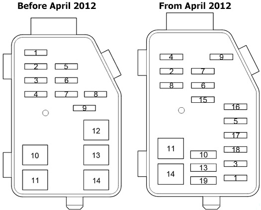
| № | Fuse | A | Circuit |
|---|---|---|---|
| 1 | ECU-B | 10 | Multiplex communication system, sliding door closer system, air conditioning system, wireless remote control system |
| 2 | ETCS | 10 | 1TR-FE (from Apr. 2012), 2TR-FE: Electronic throttle control system |
| A/F | 15 | 1KD-FTV with DPF: A/F heater, Electronically controlled fuel pump | |
| 3 | PSD | 25 | Sliding door closer system |
| 4 | ABS SOL | 25 | Anti-lock brake system |
| 5 | TVSS | 15 | |
| 6 | DOME | 10 | Personal lights, interior lights, step lights, gauges and meters |
| 7 | RADIO | 15 | Audio system |
| 8 | ALT-S | 7.5 | Charging |
| 9 | D.C.C | 30 | All components in "RADIO” and "DOME” fuses |
| 10 | HEAD | 40 | Headlight |
| 11 | ABS MTR | 40 | Anti-lock brake system |
| 12 | - | - | Before Apr. 2012: - |
| 13 | RR DOOR | 30 | Sliding door closer system |
| 14 | AM2 | 30 | All components in "IGN” and "MET IGN” fuses, starting system, multiport fuel injection system/sequential multiport fuel injection system |
| 15 | - | - | From Apr. 2012: - |
| 16 | - | - | From Apr. 2012: - |
| 17 | - | - | From Apr. 2012: - |
| 18 | - | - | From Apr. 2012: - |
| 19 | - | - | From Apr. 2012: - |
Advertisements