
Advertisements
Fuse box diagram (fuse layout), location, and assignment of fuses and relays Toyota Celica (T23/T230) (1999, 2000, 2001, 2002, 2004, 2005, 2006).
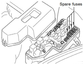
Checking and Replacing Fuses
The fuses are designed to blow before the entire wiring harness is damaged. If any of the electrical components do not operate, a fuse may have blown. If this happens, check and replace the fuses as necessary.
- Turn the engine switch off and turn off all electrical accessories.
- Open the fuse box cover.
- See diagrams below for details about which fuse to check.
- Remove the fuse.
- Check if the fuse is blown – if the thin wire inside is broken, the fuse has blown.
- Replace the blown fuse with a new fuse of an appropriate amperage rating.
Notice
- Never use a fuse of a higher amperage rating than that indicated, or use any other object in place of a fuse, even as a temporary fix. This can cause extensive damage or even fire.
- Always use a genuine Toyota fuse or equivalent.
- Do not modify the fuses or fuse boxes.
- If the replaced fuse blows again, have the vehicle inspected by any authorized Toyota dealer or repairer, or another duly qualified and equipped professional.
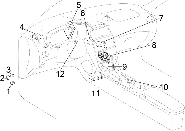
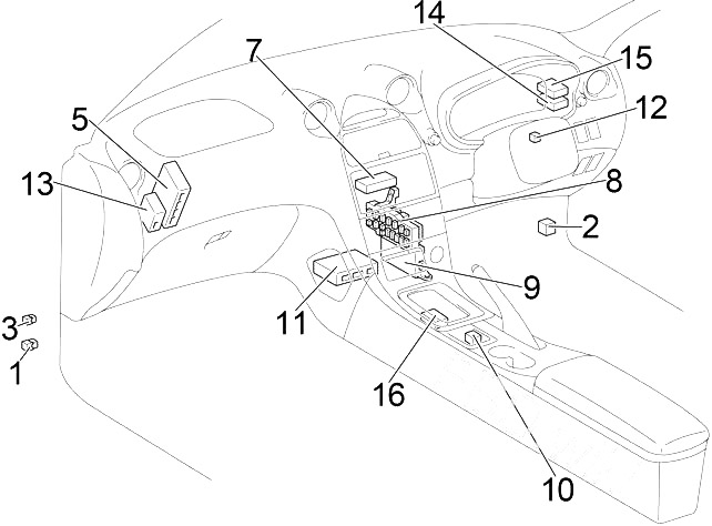
Passenger Compartment
Left-hand drive
Right-hand drive
- Rear Fog Light Relay
- Turn Signal Flasher Relay
- Front Fog Light Relay
- 2002-2005: Headlight Beam Level Control ECU
- 2002-2005: Skid Control ECU (with VSC)
- 1999-2002 (LHD): ABS ECU
- A/C Control Assembly
- Fuse Box
- Body ECU
- 2002-2005:Seat Heater Relay
- Center Airbag Sensor Assembly
- Transponder Key Amplifier
- 2002-2005 (Australia): Headlight Beam Level Control ECU
1999-2002 (RHD): ABS ECU - 2002-2005 (RHD): Headlight Beam Level Control ECU
- 2002-2005 (Australia): Cruise Control ECU
- 2002-2005 (Australia): Shift Lock Control ECU
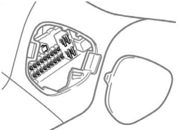
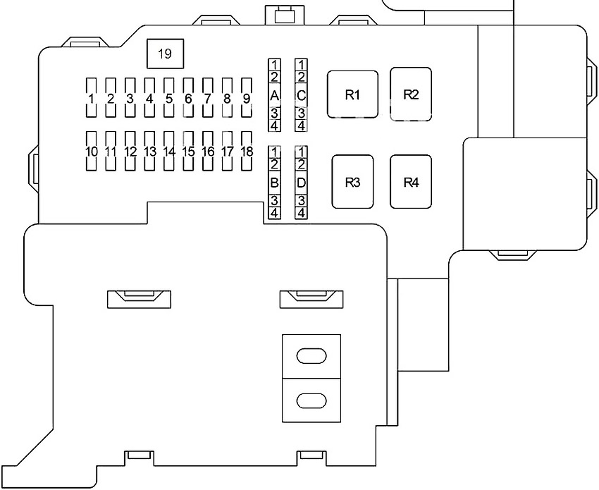
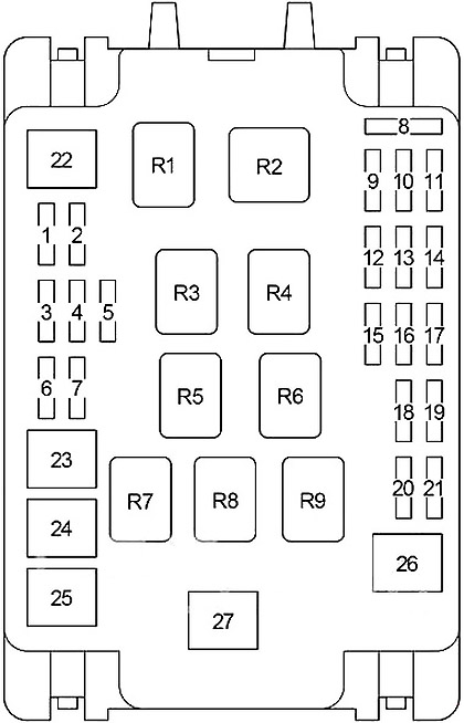
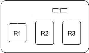
Passenger Compartment Fuse Box Diagram
The fuse panel is located behind the cover on the passenger’s side of the central console.
Advertisements
| № | Fuse | A | Circuit |
|---|---|---|---|
| 1 | S/ROOF | 15 | Electric moon roof |
| 2 | FL P/W | 20 | Power windows |
| 3 | STOP | 10 | Stop lights, anti−lock brake system, high mounted stoplight, multiport fuel injection system/sequential multiport fuel injection system, electronically controlled automatic transmission system, cruise control system |
| 4 | SRS-IG | 7.5 | SRS airbag system |
| 5 | WASHER | 15 | Windshield washer, rear window washer |
| 6 | RADIO | 15 | Audio system |
| 7 | TURN | 7.5 | Turn signal lights |
| 8 | HTR | 10 | Air conditioning system |
| 9 | TAIL | 10 | Tail lights, instrument panel lights, license plate lights, front side maker lights |
| 10 | CIG | 15 | Cigarette lighter |
| 11 | AM1 | 25 | Starting system, “CIG”, “ECU ACC”, “SRS−IG”, “WASHER”, “WIPER”, “BK/UP LP”, “TENS RDC”, “DEF RLY”, “BODY ECU−IG”, “TURN”, “HTR”, “WARNING”, “FAN RLY”, “ABS−IG” and “ECU−IG” fuses |
| 12 | DOOR | 20 | Power door lock system |
| 13 | FR FOG | 15 | Front fog lights |
| 14 | OBD | 7.5 | On−board diagnosis system |
| 15 | WIPER | 25 | Windshield wipers |
| 16 | MIR HTR | 10 | Mirror heater |
| 17 | RR WIPER | 15 | Rear window wiper |
| 18 | FR P/W | 20 | Power windows |
| 19 | DEF | 30 | Rear window defogger |
| A1 | MPX-B | 7.5 | Wireless remote control system |
| A2 | RR FOG | 7.5 | Rear fog light |
| A3 | DOME | 7.5 | Clock, interior light |
| A4 | ECU-B | 7.5 | Air conditioning system, gauges and meters |
| B1 | WARNING | 5 | Charging system, gauges and meters |
| B2 | ECU-IG | 5 | Cruise control system |
| B3 | ABS-IG | 5 | Anti−lock brake system |
| B4 | FAN RLY | 5 | Electric cooling fan |
| C1 | PANEL 1 | 7.5 | Glove box light, instrument panel lights |
| C2 | PANEL 2 | 7.5 | Front fog lights, instrument panel lights, instrument cluster lights |
| C3 | ECU-ACC | 7.5 | Clock, audio system, power rear view mirror controls, power antenna |
| C4 | - | - | - |
| D1 | BK/UP LP | 5 | Back−up lights |
| D2 | DEF RLY | 5 | Power windows, rear window defogger |
| D3 | BODY ECU-IG | 5 | Multiplex communication system |
| D4 | TENS RDC | 5 | Electronically controlled automatic transmission system, shift lock control system, electric moon roof, power antenna |
| R1 | Ignition (IG1) | ||
| R2 | Tail light (TAIL) | ||
| R3 | Mirror heater (MIR HTR) | ||
| R4 | Rear window defogger (DEF) | ||
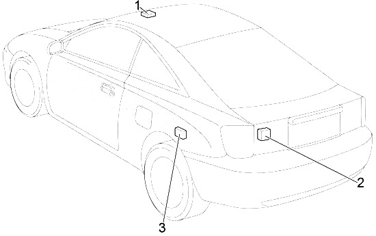
- Moon Roof Control Relay and Motor
- Rear Wiper Motor and Relay
- Door Control Receiver
Engine Compartment
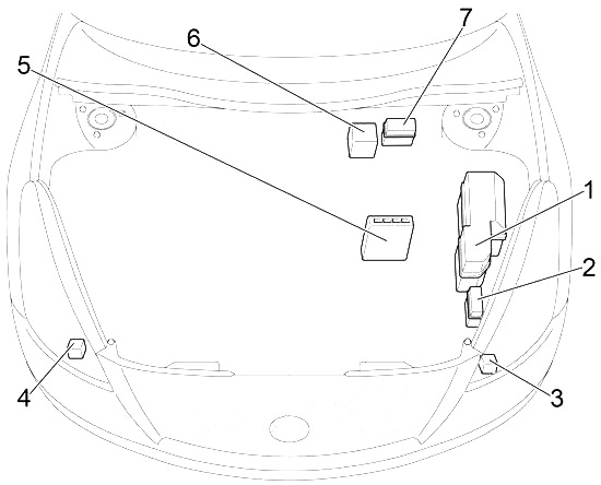
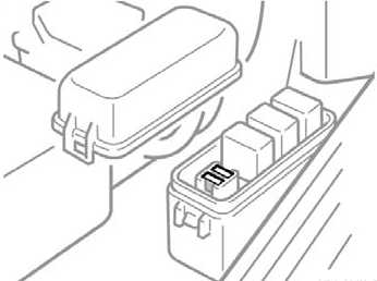
- Fuse Box
- Relay Box №1
- 2002-2005: Air Pump Relay
- 2002-2005: Headlight Cleaner Relay
- Engine ECU (M/T) or Engine and ECT ECU (A/T)
- 2002-2005: ABS & TRC & VSC Actuator (with VSC)
2002-2005: Skid Control ECU with Actuator (without VSC) - 2002-2005: Relay Box №2
Advertisements
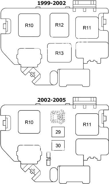
Engine Compartment Fuse Box Diagram
| № | Fuse | A | Circuit |
|---|---|---|---|
| 1 | S-HTR | 20 | 2002-2005: Seat heater |
| AUTO ANTENNA | 15 | USA: Power antenna | |
| 2 | HEAD LH UPR | 10 | Left−hand headlight (high beam) |
| 3 | HEAD RH UPR | 20 | Right−hand headlight (high beam) (HEAD RH UPR DRL №2) |
| 4 | HEAD LVL | 7.5 | Daytime running light system, headlight beam level control system |
| DRL №3 | 7.5 | Daytime running light system | |
| 5 | HEAD RH LWR | 10 | 1999-2002: Right−hand headlight (low beam) |
| 15 | 2002-2005: Right−hand headlight (low beam) | ||
| 6 | HEAD LH LWR | 10 | 1999-2002: Left−hand headlight (low beam) |
| 15 | 2002-2005: Left−hand headlight (low beam) | ||
| 7 | ABS №2 | 25 | Anti−lock brake system |
| 8 | - | - | - |
| 9 | - | - | - |
| 10 | HORN | 10 | Horn |
| 11 | ALT-S | 7.5 | Charging system |
| 12 | - | - | - |
| 13 | EFI №1 | 10 | Multiport fuel injection system/sequential multiport fuel injection system |
| 7.5 | Multiport fuel injection system/sequential multiport fuel injection system | ||
| 14 | DCC | 25 | “RADIO”, “DOME”, “MPX−B” and “ECU−B” fuses |
| 15 | - | - | - |
| 16 | EFI №2 | 7.5 | Multiport fuel injection system/sequential multiport fuel injection system, emission control system |
| 10 | Multiport fuel injection system/sequential multiport fuel injection system, emission control system | ||
| 17 | EFI | 20 | Multiport fuel injection system/sequential multiport fuel injection system, “EFI №1” and “EFI №2” fuses |
| 15 | Europe 2ZZ-GE: Multiport fuel injection system/sequential multiport fuel injection system, “EFI №1” and “EFI №2” fuses | ||
| 18 | ST | 7.5 | Starting system, multiport fuel injection system/sequential multiport fuel injection system |
| 19 | AM2 | 7.5 | Starting system |
| 20 | IG2 | 15 | Starting system, multiport fuel injection system/sequential multiport fuel injection system |
| 21 | HAZ | 15 | Emergency flashers |
| 10 | Australia, USA: Emergency flashers | ||
| 22 | HTR | 50 | Air conditioning system |
| 23 | RDI | 30 | Electric cooling fan |
| 24 | ABS №1 | 40 | '99-'02: Anti−lock brake system |
| 50 | '02-'05: Anti−lock brake system | ||
| 25 | CDS | 30 | Electric cooling fan |
| 26 | MAIN | 40 | Starting system, daytime running light system, “ST” fuse |
| 50 | Europe 2ZZ-GE: Starting system, daytime running light system, “ST” fuse | ||
| 27 | ALT | 120 | Cooling system, electric cooling fan, starting system, rear window defogger, tail lights, “ABS №1”, “ABS №2”, “HTR”, “FR P/W”, “FL P/W”, “DOOR”, “OBD”, “STOP”, “S/ROOF”, “MIR HTR”, “FR FOG” and “AM1” fuses |
| R1 | Horn | ||
| R2 | Headlight (HEAD) | ||
| R3 | Circuit opening (Fuel pump (C/OPN)) | ||
| R4 | Engine control unit (EFI) | ||
| R5 | Electric cooling fan (FAN №1) | ||
| R6 | Ignition (IG2) | ||
| R7 | Electric cooling fan (FAN №2) | ||
| R8 | Electric cooling fan (FAN №3) | ||
| R9 | Air conditioner compressor clutch (MG/C) | ||
| № | Fuse | A | Circuit |
|---|---|---|---|
| 28 | ETCS | 10 | Electronic throttle control system |
| 29 | A-PMP | 50 | Emission control system |
| 30 | H-LP CLNH-LP CLN | 30 | Headlamp cleaner |
| 50 | Headlamp cleaner | ||
| R10 | Starter (ST) | ||
| R11 | Heater (HTR) | ||
| R12 | Anti-lock brake system (ABS SOL) | ||
| R13 | Anti-lock brake system (ABS MTR) | ||
Advertisements
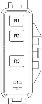
Relay Box №1
| № | Fuse | A | Circuit |
|---|---|---|---|
| 1 | HEAD LH UPR | 10 | Left-hand headlight (high beam) |
| 2 | HEAD RH UPR | 10 | Right-hand headlight (high beam), daytime running light system |
| R1 | - | ||
| R2 | - | ||
| R3 | Daytime running light system (DRL №2 DIMMER) | ||
Relay Box №2
| № | Fuse | A | Circuit |
|---|---|---|---|
| 1 | VSC | 7.5 | - |
| R1 | (VSC MTR) | ||
| R2 | (MTR CUT) | ||
| R3 | (VSC SOL) | ||
Advertisements