Advertisements
Fuse box diagram (fuse layout), location, and assignment of fuses and relays Toyota Camry (XV10) (1991, 1992, 1993, 1994, 1995, 1996).
Checking and Replacing Fuses
The fuses are designed to blow before the entire wiring harness is damaged. If any of the electrical components do not operate, a fuse may have blown. If this happens, check and replace the fuses as necessary.
- Turn the engine switch off (with a smart key system – turn the “ENGINE START STOP” switch off) and turn off all electrical accessories.
- Open the fuse box cover.
- See diagrams below for details about which fuse to check.
- Remove the fuse.
- Check if the fuse is blown – if the thin wire inside is broken, the fuse has blown.
- Replace the blown fuse with a new fuse of an appropriate amperage rating.
Notice
- Never use a fuse of a higher amperage rating than that indicated, or use any other object in place of a fuse, even as a temporary fix. This can cause extensive damage or even fire.
- Always use a genuine Toyota fuse or equivalent.
- Do not modify the fuses or fuse boxes.
- If the replaced fuse blows again, have the vehicle inspected by any authorized Toyota dealer or repairer, or another duly qualified and equipped professional.
Passenger Compartment
Left-hand drive
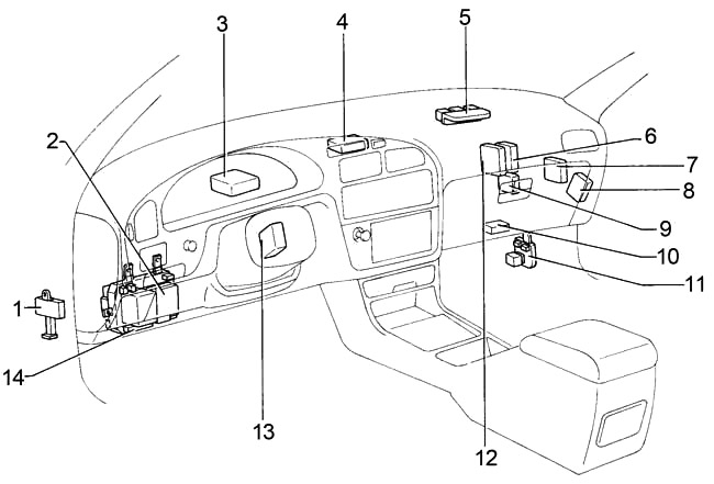
- Fuse Box (Left Kick Panel)
- Integration Relay
- Behind Combination Meter
- A/C Amplifier (Auto A/C)
- Behind Glove Box
- Cruise Control ECU
- ABS ECU
- Door Lock Comfort Relay
- A/C Amplifier (Manual A/C)
- Cooling Fan ECU
- Fuse Box (Right Kick Panel)
- Engine and ECT ECU (A/T) / Engine ECU (M/T)
- Daytime Running Light Relay
- Fuse Box
Right-hand drive
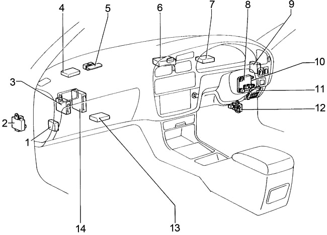
- Theft Deterrent and Door Lock ECU
- Fuse Box (Right Kick Panel)
- Cruise Control ECU
- A/C Amplifier (Manual A/C)
- Behind Glove Box
- A/C Amplifier (Auto A/C)
- Behind Combination Meter
- Fuse Box
- ABS ECU
- Integration Relay
- Fuse Box
- Cooling Fan ECU
- Engine and ECT ECU (A/T) / Engine ECU (M/T)
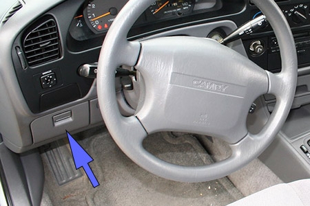
Passenger Compartment Fuse Box Diagram
The fuse panel is located behind the coin tray on the driver’s side of the dashboard.
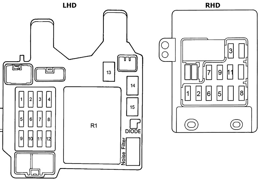
| № | Fuse | A | Circuit(s) protected |
|---|---|---|---|
| 1 | ECU-IG | 15 | A/C Triple Pressure SW (A/C Dual and Single Pressure SW) |
| ABS Actuator and ECU (TMM Made) | |||
| ABS ECU (TMC Made) | |||
| Auto Antenna Motor and Relay | |||
| Buckle SW LH | |||
| Buckle SW RH | |||
| Combination Meter (Malfunction Indicator Light) | |||
| Combination Meter (Rear Light Warning Light) | |||
| Cooling Fan ECU (1MZ–FE) | |||
| Cruise Control ECU | |||
| Diode (for Tension Reducer) (C/P) | |||
| Electronic Controlled Transmission Solenoid | |||
| Engine Coolant Temp. Sensor (Water Temp. Sensor) (for Cooling Fan) (1MZ–FE) | |||
| Junction Connector | |||
| Junction Connector (W/G) | |||
| Shift Lock ECU | |||
| Radiator Fan Relay (Coil Side) | |||
| Radiator Fan Relay № 2 (Coil Side) | |||
| 2 | GAUGE | 10 | A/C Triple Pressure SW (A/C Dual and Single Pressure SW) |
| A/C Magnetic Clutch and Lock Sensor | |||
| ABS Actuator and ECU (TMM Made) | |||
| ABS Actuator (TMC Made) | |||
| ABS Relay | |||
| A/C Evaporator Temp. Sensor | |||
| ABS ECU (TMC Made) | |||
| Air Inlet Control Servo Motor | |||
| Air Vent Mode Control Servo Motor | |||
| Back–Up Light SW (M/T) | |||
| Brake Fluid Level SW | |||
| Combination Meter | |||
| Cruise Control ECU | |||
| Data Link Connector 1 (Check Connector) | |||
| Data Link Connector 2 (TDCL (Toyota Diagnostic Communication Link)) | |||
| Daytime Running Light Relay (Main) | |||
| Door Lock Control Relay | |||
| Engine Controlled Transmission Pattern Select SW | |||
| Engine Control Module (Engine and Electronic Controlled Transmission ECU) | |||
| Fuel Pump and Sender | |||
| Generator (Alternator) | |||
| Heater Control SW (for Push Control SW Type) | |||
| Air Vent Mode Control SW (for Lever Control SW Type) | |||
| Igniter | |||
| Junction Connector | |||
| Integration Relay | |||
| Light Failure Sensor | |||
| Oil Pressure SW | |||
| O/D Main SW and A/T Indicator Light (Shift Lever) | |||
| Park/Neutral Position SW (Neutral Start SW) (A/T) | |||
| Parking Brake SW | |||
| Rear Window Defogger SW | |||
| Back–up Light LH [Rear Comb. Light LH] | |||
| Back–up Light RH [Rear Comb. Light RH] | |||
| Vehicle Speed Sensor (Speed Sensor) | |||
| Water Temp. Sender | |||
| Power Main Relay (Coil Side) | |||
| Heater Relay (Coil Side) | |||
| A/C Magnetic Clutch Relay | |||
| 3 | STOP | 15 | ABS Actuator and ECU |
| Cruise Control Actuator | |||
| Cruise Control ECU | |||
| Engine Control Module (Engine and Electronic Controlled Transmission ECU) | |||
| High Mount Stop Light | |||
| Light Failure Sensor | |||
| Noise Filter (for Stop Light) | |||
| Stop Light LH [Rear Comb. Light LH] | |||
| Stop Light RH [Rear Comb. Light RH] | |||
| Shift Lock ECU | |||
| Stop Light SW | |||
| 4 | SEAT HTR | 15 | Seat Heater |
| 5 | WIPER | 20 | Front Wiper Motor |
| Washer Motor | |||
| Junction Connector (W/G) | |||
| Rear Wiper Motor (W/G) | |||
| 6 | TURN | 7.5 | Turn Signal Flasher |
| Combination Meter (Turn Signal Indicator Light) | |||
| Combination SW (Turn Signal SW) | |||
| Front turn Signal Light LH | |||
| Front turn Signal Light RH | |||
| Hazard SW | |||
| Junction Connector | |||
| Junction Connector (W/G) | |||
| Rear Turn Signal Light LH [Rear Comb. Light LH] | |||
| Rear Turn Signal Light RH [Rear Comb. Light RH] | |||
| 7 | IGN | 7.5 | Center Airbag Sensor Assembly |
| Combination Meter | |||
| Combination Meter (Charge Warning Light) | |||
| Generator (Alternator) | |||
| Junction Connector | |||
| EFI Main Relay (Coil Side) | |||
| 8 | CIG/RADIO | 15 | Auto Antenna Motor and Relay |
| Center Airbag Sensor Assembly | |||
| Cigarette Lighter | |||
| Clock | |||
| Junction Connector | |||
| Junction Connector (W/G) | |||
| Key Interlock Solenoid | |||
| Radio and Player (w/o CD Player) | |||
| Remote Control mirror SW | |||
| Remote Control Mirror LH | |||
| Remote Control Mirror RH | |||
| Shift Lock ECU | |||
| Stereo Component Amplifier | |||
| 9 | MIR HTR | 10 | Diode (for Idle–Up) |
| Engine Control Module (Engine and Electronic Controlled Transmission ECU) | |||
| 10 | TAIL or TAIL (RH) | 15 | A/C SW |
| Ashtray Illumination | |||
| Blower SW | |||
| Cigarette Lighter Illumination | |||
| Combination Meter | |||
| Combination Meter (Meter Illmination) | |||
| Combination Meter (A/T Indicator Light) | |||
| Diode (for Idle–Up) | |||
| Engine Controlled Transmission Pattern Select SW | |||
| Engine Control Module (Engine and Electronic Controlled Transmission ECU) | |||
| Front Clearance Light LH | |||
| Front Clearance Light RH | |||
| Front Side Marker LH | |||
| Front Side Marker RH | |||
| Glove Box Light | |||
| Glove Box Light SW | |||
| Hazard SW | |||
| Heater Control SW (for Push Control SW Type) | |||
| Junction Connector | |||
| License Plate Light | |||
| Light Failure Sensor | |||
| O/D Main SW and A/T Indicator Light (Shift Lever) | |||
| Radio and Player | |||
| Rear Window Defogger SW | |||
| Rheostat | |||
| Taillight LH [Rear Comb. Light LH] | |||
| Taillight RH [Rear Comb. Light RH] | |||
| 11 | SRS | 7.5 | Center Airbag Sensor Assembly |
| Combination Meter | |||
| Combination Meter (SRS Warning Light) | |||
| Junction Connector (for Airbag System) | |||
| 12 | TAIL (LH) | 15 | |
| 13 | AM1 | 40 | Ignition SW (AM1) |
| TURN, GAUGE, ECU–IG, CIG/RADIO, WIPER fuses | |||
| Engine Control Module (Engine and Electronic Controlled Transmission ECU) | |||
| Clutch Start SW (M/T) | |||
| Park/Neutral Position SW (Neutral Start SW) (A/T) | |||
| Starter Relay (Coil Side) | |||
| 14 | POWER | 30 | Back Door Lock Control SW |
| Back Door Lock Motor (W/G) | |||
| Door Lock Control Relay | |||
| Door Key Lck and Unlock SW LH (Ex. C/P) | |||
| Door Key Lck and Unlock SW RH (Ex. C/P) | |||
| Door Lock Control SW RH | |||
| Door Lock Motor and Door Unlock | |||
| Detection SW Front LH | |||
| Door Lock Motor and Door Unlock | |||
| Detection SW Front RH | |||
| Junction Connector | |||
| Junction Connector (W/G) | |||
| Moon Roof Control Relay | |||
| Moon Roof Control SW and Personal Light (w/ Moon Roof) (EX. W/G) | |||
| Moon Roof Limit SW (EX. W/G) | |||
| Moon Roof Motor (EX. W/G) | |||
| Power Seat Control SW | |||
| Power Seat Motor (for Front Vertical Control) | |||
| Power Seat Motor (for Rear Vertical Control) | |||
| Power Seat Motor (for Slide control) | |||
| Power Seat Motor (for Reclining Control) | |||
| Power Window Control SW Front RH | |||
| Power Window Control SW Rear LH (EX. C/P) | |||
| Power Window Control SW Rear RH (EX. C/P) | |||
| Power Window Master SW and Door Lock control SW LH | |||
| Power Window Motor Front LH | |||
| Power Window Motor Front RH | |||
| Power Window Motor Rear LH (EX. C/P) | |||
| Power Window Motor Rear RH (EX. C/P) | |||
| Power Main Relay (Point Side) | |||
| 15 | DEFOG | 40 | Rear Window Defogger |
| R1 | Integration Relay | ||
Advertisements
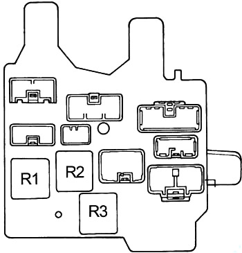
| № | Relay |
|---|---|
| R1 | Power Main Relay |
| R2 | Taillight |
| R3 | Defogger |
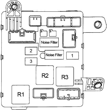
| № | Fuse | A | Circuit(s) protected |
|---|---|---|---|
| 13 | AM1 | 40 | Ignition SW (AM1) |
| TURN, GAUGE, ECU–IG, CIG/RADIO, WIPER fuses | |||
| Engine Control Module (Engine and Electronic Controlled Transmission ECU) | |||
| Clutch Start SW (M/T) | |||
| Park/Neutral Position SW (Neutral Start SW) (A/T) | |||
| Starter Relay (Coil Side) | |||
| 14 | POWER | 30 | Back Door Lock Control SW |
| Back Door Lock Motor (W/G) | |||
| Door Lock Control Relay | |||
| Door Key Lck and Unlock SW LH (Ex. C/P) | |||
| Door Key Lck and Unlock SW RH (Ex. C/P) | |||
| Door Lock Control SW RH | |||
| Door Lock Motor and Door Unlock | |||
| Detection SW Front LH | |||
| Door Lock Motor and Door Unlock | |||
| Detection SW Front RH | |||
| Junction Connector | |||
| Junction Connector (W/G) | |||
| Moon Roof Control Relay | |||
| Moon Roof Control SW and Personal Light (w/ Moon Roof) (EX. W/G) | |||
| Moon Roof Limit SW (EX. W/G) | |||
| Moon Roof Motor (EX. W/G) | |||
| Power Seat Control SW | |||
| Power Seat Motor (for Front Vertical Control) | |||
| Power Seat Motor (for Rear Vertical Control) | |||
| Power Seat Motor (for Slide control) | |||
| Power Seat Motor (for Reclining Control) | |||
| Power Window Control SW Front RH | |||
| Power Window Control SW Rear LH (EX. C/P) | |||
| Power Window Control SW Rear RH (EX. C/P) | |||
| Power Window Master SW and Door Lock control SW LH | |||
| Power Window Motor Front LH | |||
| Power Window Motor Front RH | |||
| Power Window Motor Rear LH (EX. C/P) | |||
| Power Window Motor Rear RH (EX. C/P) | |||
| Power Main Relay (Point Side) | |||
| 15 | DEFOG | 40 | Rear Window Defogger |
| R1 | Defogger | ||
| R2 | Power Main Relay | ||
| R3 | Taillight | ||
Fuse Box (Left Kick Panel)
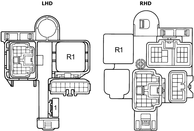
| № | A | Circuit(s) protected |
|---|---|---|
| 1 | 10 | LHD: Starter |
| R1 | Turn Signal Flasher | |
Fuse Box (Right Kick Panel)
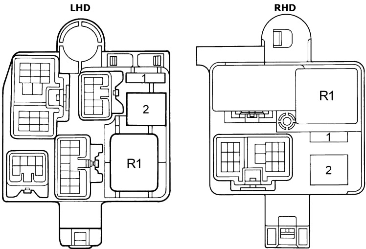
| № | A | Circuit(s) protected |
|---|---|---|
| 1 | 10 | A/C |
| 2 | 40 | Heater |
| R1 | Heater | |
Behind Glove Box
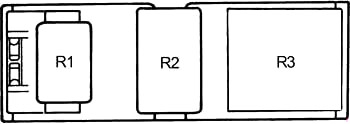
| № | Relay |
|---|---|
| R1 | Rear Fog Light |
| or | |
| Starter | |
| R2 | Circuit Opening Relay |
| R3 | Turn Signal Flasher |
Advertisements
Engine Compartment
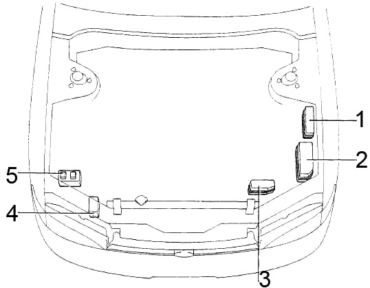
- Fuse Box
- Fuse Box
- Fuse Box
- ABS Relay (TMC)
- ABS Actuator and ECU (TMM)
Engine Compartment Fuse Box Diagram (1991-1994)
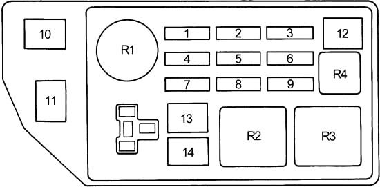
| № | Fuse | A | Circuit(s) protected |
|---|---|---|---|
| 1 | STARTER | 10 | Starting system, electronic fuel injection system |
| 2 | ALT-S | 7.5 | Charging system |
| 3 | EFI | 15 | Electronic fuel injection system |
| 4 | HEAD (RH) | 15 | Right-hand headlight |
| or | |||
| HEAD HI (RH) | Right-hand headlight (high beam) | ||
| 5 | DOME | 20 | Radio, cassette tape player, compact disc player, power antenna, interior light, personal lights, door courtesy lights, ignition switch light, trunk room light, electronic moon roof system, instrument panel lights, door lock and theft deterrent system, locking with wireless remote control system |
| 6 | HAZ-HORN | 15 | Emergency flashers, horns |
| 7 | HEAD (LH) | 15 | Left-hand headlight |
| or | |||
| HEAD HI (LH) | |||
| 8 | - | - | Not used |
| 9 | AM2 | 30 | Ignition system, electronic fuel injection system |
| 10 | ALT | 100 | Charging system |
| 11 | ABS | 60 | Anti-lock brake system |
| 12 | ST MAIN | 30 | Starting system |
| 13 | - | - | Not used |
| 14 | - | - | Not used |
| R1 | EFI Main Relay | ||
| R2 | Not used | ||
| R3 | Headlight | ||
| R4 | Horn | ||
Engine Compartment Fuse Box Diagram (1994-1996)
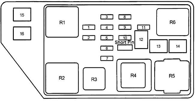
| № | Fuse | A | Circuit(s) protected |
|---|---|---|---|
| 1 | EFI | 15 | Electronic Controlled Transmission Solenoid |
| Engine Control Module | |||
| Data Link Connector 1 (Check Connector) | |||
| Fuel Pump and Sender | |||
| Heated Oxygen Sensor (Bank 1 Sensor 2) | |||
| Heated Oxygen Sensor (Bank 1 Sensor 1) (1MZ–FE) | |||
| Heated Oxygen Sensor (Bank 2 Sensor 1) (1MZ–FE) | |||
| Idle Air Control Valve (ISC Valve) | |||
| Junction Connector (1MZ–FE) | |||
| Mass Air Flow (Air Flow Meter) (1MZ–FE) | |||
| VSV (for A/C Idle–Up) | |||
| VSV (for EGR System) (1MZ–FE) | |||
| VSV (for Fuel Pressure Up) | |||
| VSV (for Intake Air Control) (1MZ–FE) | |||
| EFI Main Relay (Point Side) | |||
| Circuit Opening Relay (Coil Side) | |||
| 2 | HORN | 10 | Horn Relay |
| Horn LH | |||
| Horn RH | |||
| Combination SW (Horn SW) | |||
| 3 | OBD | 7.5 | Date Ling Connector 3 |
| 4 | HAZ | 10 | Combination Meter (Turn Signal Indicator Light) |
| Combination SW (Turn Signal SW) | |||
| Front turn Signal Light LH | |||
| Front turn Signal Light RH | |||
| Rear Turn Signal Light LH [Rear Comb. Light LH] | |||
| Rear Turn Signal Light RH [Rear Comb. Light RH] | |||
| Hazard SW | |||
| Junction Connector | |||
| Junction Connector (W/G) | |||
| 5 | DOME | 20 | Radio and Player (w/o CD Player) |
| Auto Antenna Motor and Relay | |||
| Door Courtesy SW Front LH | |||
| Door Courtesy SW Front RH | |||
| Door Courtesy SW Rear LH | |||
| Door Courtesy SW Rear RH | |||
| Door Key Cylinder Light and SW | |||
| Injector Key Cylinder Light | |||
| Integration Relay | |||
| Interior Light | |||
| Junction Connector | |||
| Junction Connector (W/G) | |||
| Luggage Compartment Light | |||
| Luggage Compartment Light SW | |||
| Moon Roof Control Relay | |||
| Moon Roof Control SW and Personal Light (w/ Moon Roof) (EX. W/G) | |||
| Stereo Component Amplifier | |||
| Vanity Light LH | |||
| Vanity Light RH | |||
| Diode | |||
| 6 | HEAD (LH) | 15 | Combination SW (Light Control SW) |
| Headlight Lo LH | |||
| Headlight Hi LH | |||
| HEAD (LH-UPR) | 15 | Combination Meter (High Beam Indicator Light) | |
| Headlight Hi LH | |||
| Daytime Running Light Relay № 4 (Coil Side) | |||
| 7 | HEAD (RH) | 15 | Combination SW (Light Control SW) |
| Combination Meter (High Beam Indicator Light) | |||
| Headlight Lo RH | |||
| Headlight Hi RH | |||
| HEAD (RH-UPR) | 15 | Headlight Hi RH | |
| Daytime Running Light Relay № 3 (Coil Side) | |||
| 8 | ALT-S | 7.5 | Generator (Alternator) |
| 9 | AM2 | 30 | Engine Control Module |
| Igniter | |||
| Ignition Coil | |||
| Injector № 1 | |||
| Injector № 2 | |||
| Injector № 3 | |||
| Injector № 4 | |||
| Injector № 5 (1MZ–FE) | |||
| Injector № 6 (1MZ–FE) | |||
| Ignition SW and Unlock Warning SW | |||
| Ignition Coil № 1 (1MZ–FE) | |||
| Ignition Coil № 2 (1MZ–FE) | |||
| Ignition Coil № 3 (1MZ–FE) | |||
| Ignition Coil № 4 (1MZ–FE) | |||
| Ignition Coil № 5 (1MZ–FE) | |||
| Ignition Coil № 6 (1MZ–FE) | |||
| Noise Filter (for Ignition System) | |||
| EFI Main Relay (Coil Side) | |||
| 10 | ECU-B | 15 | ABS ECU (TMC Made) |
| Daytime Running Light Relay (Main) | |||
| 11 | - | - | Not Used |
| 12 | MAIN | 40 | HEAD (LH), HEAD (RH), DRL, HEAD (LWR–LH), HEAD (LWR–RH), STARTER fuses |
| Daytime Running Light Relay (Main) | |||
| Dimmer SW [Comb. SW] | |||
| Integration Relay (Light Control SW [Comb. SW]) | |||
| 13 | RDI FAN | 30 | |
| 14 | CDS FAN | 30 | A/C Condenser Fan Motor (5S–FE) |
| Radiator Fan Motor (5S–FE) | |||
| Radiator Fan Relay (Point Side) | |||
| Radiator Fan Relay № 2 (Coil Side) | |||
| Radiator Fan Relay № 2 (Point Side) | |||
| 15 | ALT | 100 | Charging system |
| 16 | ABS | 60 | Anti–lock brake system |
| R1 | EFI Main Relay | ||
| R2 | Starter | ||
| R3 | Horn | ||
| R4 | Headlight | ||
| R5 | Radiator Fan | ||
| R6 | Engine Main Relay | ||
Advertisements
Additional Fuse Box
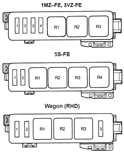
| № | Fuse | A | Circuit(s) protected |
|---|---|---|---|
| 1 | HEAD (LWR LH) | 15 | With DRL: Headlight Lo LH |
| ST | 10 | Starter | |
| 2 | HEAD (LWR RH) | 15 | With DRL: Headlight Lo RH |
| 3 | MAIN №2 | 50 | Wagon: |
| 4 | - | - | Not Used |
| R1 | 3VZ-FE: Fuel Pump | ||
| 5S-FE: Fan №3 | |||
| R2 | 3VZ-FE, 1MZ–FE: A/C Magnetic Clutch | ||
| 5S-FE: Fan №2 | |||
| Wagon: Fuel Pump (3VZ-FE) | |||
| R3 | 3VZ-FE: Dimmer (With DRL) | ||
| 5S-FE: A/C Magnetic Clutch | |||
| Wagon: A/C Magnetic Clutch | |||
| 1MZ–FE: Daytime Running Light Relay №2 | |||
| R4 | 5S-FE: Dimmer (With DRL) | ||
Relay Box
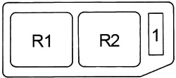
| № | Fuse | A | Circuit(s) protected |
|---|---|---|---|
| 1 | DRL | 7.5 | Daytime Running Light |
| R1 | Daytime Running Light Relay №4 | ||
| R2 | Daytime Running Light Relay №3 | ||
Advertisements
