
Advertisements
Fuse box diagram (fuse layout), location, and assignment of fuses and relays Toyota Aygo (AB10) (2005, 2006, 2007, 2008, 2009, 2010, 2011, 2012, 2013, 2014).

Checking and Replacing Fuses
The fuses are designed to blow before the entire wiring harness is damaged. If any of the electrical components do not operate, a fuse may have blown. If this happens, check and replace the fuses as necessary.
- Turn the engine switch off (with a smart key system – turn the “ENGINE START STOP” switch off) and turn off all electrical accessories.
- Open the fuse box cover.
- See diagrams below for details about which fuse to check.
- Remove the fuse.
- Check if the fuse is blown – if the thin wire inside is broken, the fuse has blown.
- Replace the blown fuse with a new fuse of an appropriate amperage rating.
Notice
- Never use a fuse of a higher amperage rating than that indicated, or use any other object in place of a fuse, even as a temporary fix. This can cause extensive damage or even fire.
- Always use a genuine Toyota fuse or equivalent.
- Do not modify the fuses or fuse boxes.
- If the replaced fuse blows again, have the vehicle inspected by any authorized Toyota dealer or repairer, or another duly qualified and equipped professional.
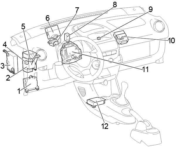
Passenger Compartment
Left-hand drive
Right-hand drive
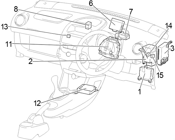
- Power Steering ECU
- Center Connector
- Multi-mode Manual Transmission ECU
- Power Window Relay
- LHD:
Before Feb. 2012: Tail Lamp Relay
From Feb. 2012: Rear Fog Lamp Relay - Door Control ECU with Receiver
- Relay Box №1
- A/C Amplifier
- LHD: Fog Lamp Relay
- LHD: Running Light Relay
- Fuse Box
- Airbag Sensor Assembly Center
- RHD: Relay Box №2
- RHD:
Before Feb. 2012:Ignition Relay (IG)
From Feb. 2012: Power Window Relay - RHD:
Before Feb. 2012:Power Window Relay
From Feb. 2012: Rear Fog Lamp Relay
Passenger Compartment Fuse Box Diagram
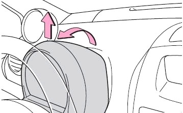
The fuses are located behind the cover on the instrument panel.
Remove the meter cover screws, by using a Phillips-head screwdriver Phillips Head. If the steering lock is engaged, please disengage it.
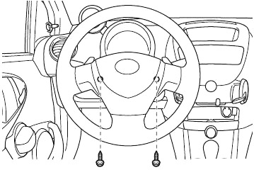
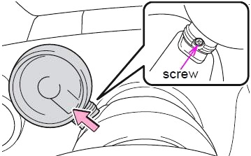
Remove the bottom screw of the tachometer, and lift and pull up on the tachometer.
Pull the meter cover forward, lift up, and remove the meter cover.
Advertisements
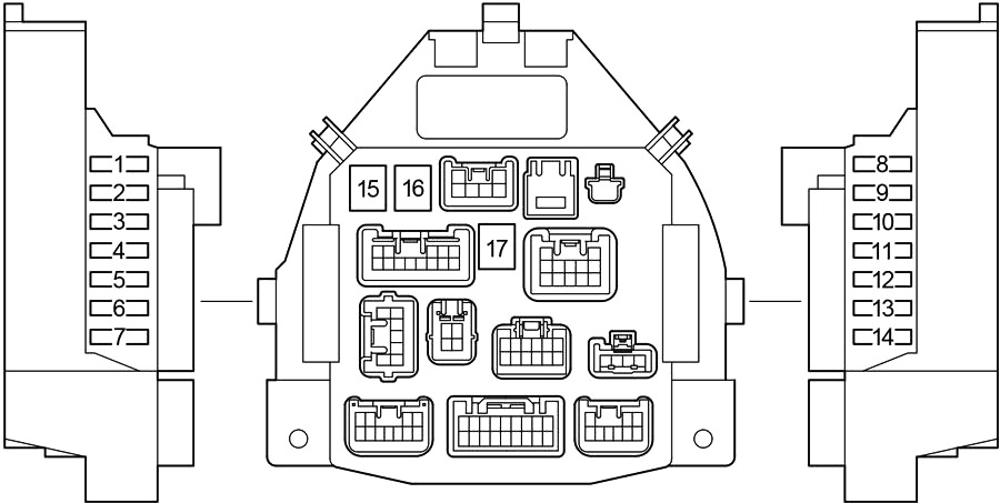
| № | Fuse | A | Circuit |
|---|---|---|---|
| 1 | STOP | 10 | Stop lights, high mounted stop light, anti−lock brake system, multi−mode manual transmission |
| 2 | D/L | 25 | Power door lock system, wireless remote control system |
| 3 | DEF | 20 | Rear window defogger |
| 4 | TAIL | 7.5 | Daytime running light system, tail lights, license plate lights, position lights, headlight beam level control system, instrument panel lights |
| 5 | OBD | 7.5 | On−board diagnosis system |
| 6 | ECU-B | 7.5 | Multi−mode manual transmission, daytime running light system, vehicle stability control system, gauges and meters, rear fog light |
| 7 | - | - | - |
| 8 | ECU-IG | 7.5 | Anti−lock brake system, vehicle stability control system, electric power steering system, electric cooling fan |
| 9 | BACK UP | 10 | Back−up lights, power door lock system, wireless remote control system, power windows, rear window defogger, tachometer, air conditioning system, heater system |
| 10 | WIP | 20 | Windshield wiper and washer, rear window wiper and washer |
| 11 | ACC | 15 | Power outlet, audio system |
| 12 | IG1 | 7.5 | Windshield wiper and washer, rear window wiper and washer, anti−lock brake system, electric power steering system, electric cooling fan, back−up lights, power door lock system, wireless remote control system, power windows, rear window defogger, tachometer, air conditioning system, heater system |
| 13 | IG2 | 15 | Multiport fuel injection system/sequential multiport fuel injection system, SRS airbag system, gauges and meters, daytime running light system, multi−mode manual transmission |
| 14 | A/C | 7.5 | Air conditioning system, power heater |
| 15 | AM1 | 40 | "ACC”, "WIP”, "ECU−IG”, "BACK UP” fuses |
| 16 | PWR | 30 | Power windows |
| 17 | HTR | 40 | Heater system, air conditioning system, "A/C” fuse |
Relay Box №1
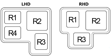
| № | Relay |
|---|---|
| R1 | Accessory (ACC) |
| R2 | Heater (HTR) |
| R3 | Rear window defogger (DEF) |
| R4 | LHD: Ignition (IG) |
Relay Box №1
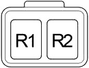
| № | Relay |
|---|---|
| R1 | Ignition (IG) |
| R2 | Fog light (FOG) |
Engine Compartment
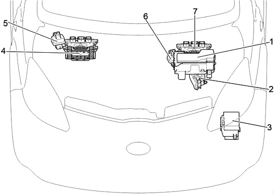
- Fuse Box
- Skid Control ECU with Actuator
- Relay Box
- LHD: Engine ECU
- LHD: Glow Plug Relay
- RHD: Glow Plug Relay
- RHD: Engine ECU
Advertisements
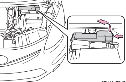
Engine Compartment Fuse Box Diagram
Push the tab in and lift the lid off.
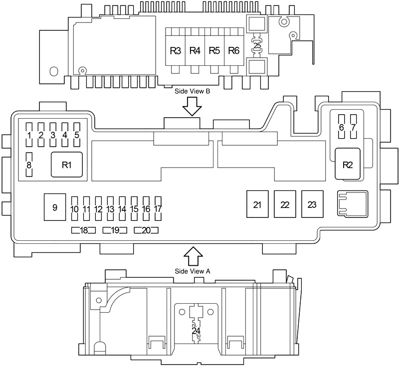
| № | Fuse | A | Designation |
|---|---|---|---|
| 1 | EFI №4 | 15 | 2WZ-TV: Multiport fuel injection system/sequential multiport fuel injection system |
| 2 | H-LP RH (HI) | 10 | Before Feb. 2012: Right−hand headlights |
| DRL | 5 | From Feb. 2012: Daytime running lights | |
| 3 | H-LP LH (HI) | 10 | Before Feb. 2012: Left−hand headlights, gauges and meters |
| FR FOG | 20 | From Feb. 2012: Front fog lights | |
| 4 | H-LP RH (LO) | 10 | Before Feb. 2012: Right−hand headlights |
| H-LP LH | 10 | From Feb. 2012: Left-hand headlights | |
| 5 | H-LP LH (LO) | 10 | Before Feb. 2012: Left−hand headlights, gauges and meters |
| H-LP RH | 10 | From Feb. 2012: Right-hand headlights | |
| 6 | STA | 7.5 | 1KR-FE: Multi−mode manual transmission, multiport fuel injection system/sequential multiport fuel injection system |
| FAN №2 | 7.5 | 2WZ-TV: Electric cooling fan | |
| 7 | EFI №2 | 7.5 | Multiport fuel injection system/sequential multiport fuel injection system, multi−mode manual transmission |
| 8 | EFI №3 | 10 | 2WZ-TV: Multiport fuel injection system/sequential multiport fuel injection system, electric cooling fan |
| MET | 5 | Gauges and meters | |
| 9 | AMT | 50 | 1KR-FE: Multi−mode manual transmission |
| RADIATOR FAN | 50 | 2WZ-TV: Electric cooling fan | |
| 10 | H-LP LH | 10 | without DRL: Left−hand headlights |
| DIMMER | 20 | Before Feb. 2012: | |
| with DRL: "H−LP LH (HI)”, "H−LP RH(HI)”, "H−LP LH (LO)”, "H−LP RH (LO)” fuses, daytime running light system | |||
| SUB-LP | 30 | From Feb. 2012: | |
| with DRL: "DRL", "FOG FR" fuses | |||
| 11 | VSC №2 | 30 | Anti−lock brake system and vehicle stability control system |
| ABS №2 | 25 | without VSC: Anti−lock brake system | |
| 12 | AM2 | 30 | Starting system, "IG1”, "IG2”, "STA” fuses |
| 13 | HAZARD | 10 | Turn signal lights, emergency flashers, gauges and meters |
| 14 | H-LP RH | 10 | Before Feb. 2012: Right−hand headlights |
| H-LP MAIN | 20 | From Feb. 2012: "H-LP LH", "H-LP RH" fuses | |
| 15 | DOME | 15 | Gauges and meters, interior light, audio system, tachometer |
| 16 | EFI | 15 | 1KR-FE: Electric cooling fan, multiport fuel injection system/sequential multiport fuel injection system |
| 25 | 2WZ-TV: Electric cooling fan, multiport fuel injection system/sequential multiport fuel injection system | ||
| 17 | HORN | 10 | Horn |
| 18 | - | 7.5 | Spare fuse |
| 19 | - | 10 | Spare fuse |
| 20 | - | 15 | Spare fuse |
| 21 | RADIATOR | 40 | Tropic: Electric cooling fan |
| 30 | Normal: Electric cooling fan | ||
| 22 | VSC №1 | 50 | Anti−lock brake system and vehicle stability control system |
| ABS №1 | 40 | without VSC: Anti−lock brake system | |
| 23 | EMPS | 50 | Electric power steering system |
| 24 | ALTERNATOR | 120 | 1KR-FE: Charging system, "EPS”, "ABS (without vehicle stability control system)”, "VSC (with vehicle stability control system)”, "RADIATOR”, "AM1”, "HTR”, "PWR”, "D/L”, "DEF”, "TAIL”, "STOP”, "OBD”, "ECU−B” fuses |
| 25 | - | - | EBD Resistor |
| R1 | Air conditioner compressor clutch (A/C MAG) | ||
| R2 | Starter (ST) | ||
| R3 | Engine control unit (EFI MAIN) | ||
| R4 | 1KR-FE: Fuel pump (C/OPN) | ||
| R5 | Horn | ||
| R6 | Electric cooling fan (FAN №1) | ||
Relay Box
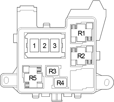
| № | Fuse | A | Circuit |
|---|---|---|---|
| 1 | - | - | - |
| 2 | PTC2 | 80 | PTC Heater |
| 3 | PTC1 | 80 | PTC Heater |
| R1 | Multi-mode manual transmission (MMT) | ||
| PTC heater (PTC1) | |||
| R2 | PTC heater (PTC2) | ||
| R3 | - | ||
| R4 | Before Feb. 2012: Headlight (H-LP) | ||
| From Feb. 2012: Daytime running light (DRL) | |||
| R5 | Dimmer (DIM) | ||
Advertisements