
Advertisements
Fuse box diagram (fuse layout), location, and assignment of fuses and relays Toyota Avalon (GSX30 / XX30) (2005, 2006, 2007, 2008, 2009, 2010, 2011, 2012).

Checking and Replacing Fuses
The fuses are designed to blow before the entire wiring harness is damaged. If any of the electrical components do not operate, a fuse may have blown. If this happens, check and replace the fuses as necessary.
- Turn the engine switch off (with a smart key system – turn the “ENGINE START STOP” switch off) and turn off all electrical accessories.
- Open the fuse box cover.
- See diagrams below for details about which fuse to check.
- Remove the fuse with the pullout tool.
- Check if the fuse is blown – if the thin wire inside is broken, the fuse has blown.
- Replace the blown fuse with a new fuse of an appropriate amperage rating.
Notice
- Never use a fuse of a higher amperage rating than that indicated, or use any other object in place of a fuse, even as a temporary fix. This can cause extensive damage or even fire.
- Always use a genuine Toyota fuse or equivalent.
- Do not modify the fuses or fuse boxes.
- If the replaced fuse blows again, have the vehicle inspected by any authorized Toyota dealer or repairer, or another duly qualified and equipped professional.
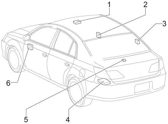
Passenger Compartment
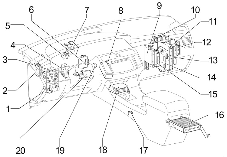
- Fuse Box
- Headlamp Leveling ECU
- Body ECU
- Distance Control ECU
- Turn Signal Flasher
- Immobiliser Code ECU (with Smart Key System)
Transponder Key ECU (without Smart Key System) - Driver Side J/B
- A/C Control Assembly
- A/C Amplifier
- Passenger Side J/B
- Engine Control Module
- Junction Connector (CAN)
- Gateway ECU
- Smart Key ECU
- Power Source Control ECU
- Stereo Component Amplifier
- Shift Lock Control ECU
- Airbag Sensor Assembly Center
- Transponder Key Amplifier
- Steering Lock ECU
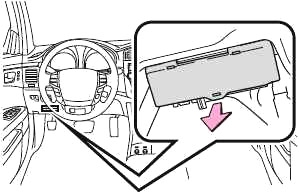
Passenger Compartment Fuse Box Diagram
The fuse panel is located below the driver’s side of the dashboard. Remove the lid.
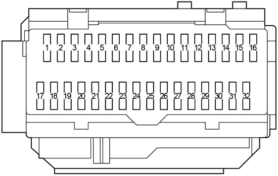
| № | Fuse | A | Circuit |
|---|---|---|---|
| 1 | RR DOOR | 25 | 2005-2009: Power window (for rear right passenger) |
| 20 | 2010-2012: Power window (for rear right passenger) | ||
| 2 | RL DOOR | 25 | 2005-2009: Power window (for rear left passenger) |
| 20 | 2010-2012: Power window (for rear left passenger) | ||
| 3 | FR DOOR | 25 | 2005-2009: Power window (front passenger), driving position memory system |
| 20 | 2010-2012: Power window (front passenger), driving position memory system | ||
| 4 | FOG | 15 | Front fog lights |
| 5 | OBD | 7.5 | On-board diagnosis system |
| 6 | MPX-B | 7.5 | Multiplex communication system |
| 7 | - | - | - |
| 8 | P/W | 25 | 2005-2009: Power widow, driving position memory system |
| FL DOOR | 20 | 2010-2012: Power window, driving position memory system | |
| 9 | FUEL OPN | 7.5 | Fuel filler door opener |
| 10 | AM1 | 7.5 | Multiport fuel injection system/sequential multiport fuel injection system, starting system, ignition system |
| 11 | A/C | 7.5 | Air conditioning system |
| 12 | S-HTR | 20 | 2008-2012: Air conditioning system |
| 13 | DOOR №2 | 25 | Multiplex communication system |
| 14 | S/ROOF | 30 | Electric moon roof |
| 15 | TAIL | 10 | Parking lights, license plate lights, tail lights, front and rear side marker lights |
| 16 | PANEL | 7.5 | Seat heaters, navigation system, emergency flasher, electronically controlled automatic transmission system, glove box light, instrument panel lights, power outlets |
| 17 | ECU IG №1 | 7.5 | 2005-2006: Center display, shift lock control system, electric moon roof, multiplex communication system |
| 10 | 2007-2012: Center display, shift lock control system, electric moon roof, multiplex communication system, tire pressure monitoring (warning) system | ||
| 18 | ECU IG №2 | 7.5 | Anti−lock brake system, dynamic laser cruise control system, automatic headlight leveling system, vehicle stability control system, multiplex communication system |
| 19 | HTR | 7.5 | Air conditioning system, instrument panel lights, electric cooling fan |
| 20 | A/C COMP | 7.5 | Air conditioning system |
| 21 | S-HTR | 20 | 2005-2007: Air conditioning system |
| 22 | GAUGE №1 | 10 | Back−up lights, navigation system, emergency flashers |
| 23 | WIP | 30 | Windshield wipers |
| 24 | RR S/SHADE | 10 | Rear electric sunshade |
| 25 | - | - | Not used |
| 26 | IGN | 10 | Multiport fuel injection system/sequential multiport fuel injection system, engine immobilizer system, SRS airbag system, front passenger occupant classification system, smart key system, starter system |
| 27 | GAUGE №2 | 7.5 | Gauges and meters, center display |
| 28 | ECU−ACC | 7.5 | Power rear view mirrors, center display, shift lock system, multiplex communication system |
| 29 | CIG | 15 | Cigarette lighter |
| 30 | PWR OUTLET | 15 | Power outlet |
| 31 | RADIO №2 | 7.5 | Audio system |
| 32 | MIR HTR | 10 | Outside rear view mirror defoggers |
Advertisements
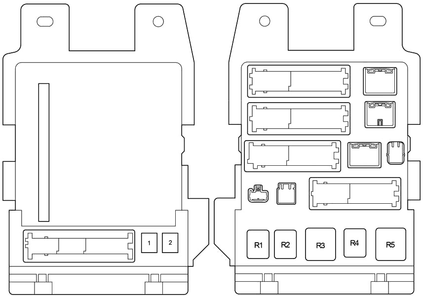
| № | Fuse | A | Circuit |
|---|---|---|---|
| 1 | P/SEAT | 30 | Power seats |
| 2 | POWER | 30 | Power windows |
| R1 | Fog Lights | ||
| R2 | Tail Lights | ||
| R3 | Accessory Relay (ACC) | ||
| R4 | Power Relay (PWR) | ||
| R5 | Ignition (IG1) | ||
- Sliding Roof Control ECU
- Outer Mirror Control ECU (RH)
- Door Control Receiver
- Navigation ECU
- Rear Sunshade Relay
- Outer Mirror Control ECU (LH)
Engine Compartment
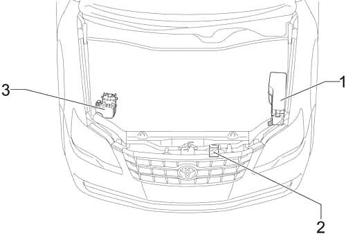
- Fuse Box
- Cooling Fan ECU
- Skid Control ECU with Actuator
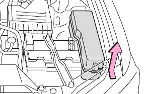
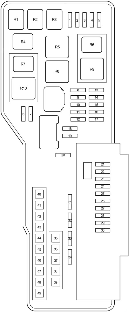
Engine Compartment Fuse Box Diagram
Push the tab in and lift the lid off.
Advertisements
| № | Fuse | A | Circuit |
|---|---|---|---|
| 1 | EFI №2 | 10 | Multiport fuel injection system/sequential multiport fuel injection system |
| 2 | STOP №2 | 7.5 | Stop lights, high mounted stoplight, vehicle stability control system, anti-lock brake system |
| 3 | RADAR CC | 7.5 | 2005-2010: Vehicle stability control system |
| 4 | HEAD RH LWR | 15 | Right-hand headlight (low beam) |
| 5 | HEAD LH LWR | 15 | Left-hand headlight (low beam) |
| 6 | STOP №3 | 7.5 | 2008-2012: Electronic controlled transmission system, multiport fuel injection system/sequential multiport fuel injection system |
| 7 | INJ | 15 | Multiport fuel injection system/sequential multiport fuel injection system |
| 8 | - | - | - |
| 9 | STOP №1 | 15 | Multiplex communication system |
| 10 | STR LOCK | 25 | 2005-2010: Steering lock system |
| 15 | 2011-2012: Steering lock system | ||
| 11 | IMMOBI | 7.5 | 2005-2007: Engine immobilizer system, smart key system |
| EFI №3 | 7.5 | 2008-2012: Smart key system, electronic controlled transmission system | |
| 12 | AMP | 30 | Audio system |
| 13 | - | - | - |
| 14 | - | - | Short Pin №1 |
| 15 | RAD №1 | 15 | Audio system, center display, navigation system |
| 16 | ECU-B | 10 | Center display, multiplex communication system |
| 17 | DOME | 7.5 | Gauges and meters, clock, front personal lights, door courtesy lights, garage door opener, rear personal lights, trunk light |
| 18 | TURN/HAZ | 15 | Turn signal lights |
| 19 | IG2 | 25 | Multiport fuel injection system/sequential multiport fuel injection system |
| 20 | - | - | - |
| 21 | S-HORN | 7.5 | Horn |
| 22 | WASHER | 20 | Windshield washer |
| 23 | A/F | 25 | Air fuel ratio sensor |
| 24 | HEAD RH UPR | 15 | Right-had headlight (high beam) |
| 25 | HEAD LH UPR | 15 | Left-hand headlight (high beam) |
| 26 | - | - | - |
| 27 | - | - | - |
| 28 | HORN | 10 | Horn |
| 29 | - | - | Horns |
| 30 | EFI №1 | 25 | Multiport fuel injection system/sequential multiport fuel injection system, fuel pump |
| 31 | ETCS | 10 | Multiport fuel injection system/sequential multiport fuel injection system |
| 32 | ALT-S | 7.5 | Charging system |
| 33 | DOOR №1 | 25 | Multiplex communication system |
| 34 | AM2 | 7.5 | Starter system |
| 35 | ALT | 120 | Charging system, "RR DEF”, "ABS/VSC NO2.” "HEATER”, "ABS/VSC №1”, "RDI FAN”, "WASHER” and "S-HORN” fuses |
| 140 | Charging system, "RR DEF”, "ABS/VSC NO2.” "HEATER”, "ABS/VSC №1”, "RDI FAN”, "WASHER” and "S-HORN” fuses | ||
| 36 | - | - | - |
| 37 | MAIN | 40 | Headlights |
| 38 | - | - | - |
| 39 | ST/AM2 | 30 | Starter system |
| 40 | HEATER | 50 | Air conditioning system |
| 41 | ABS/VSC №1 | 50 | Anti-lock brake system, vehicle stability control system |
| 42 | RDI FAN | 50 | Electric cooling fan |
| 43 | ABS/VSC №2 | 30 | Anti-lock brake system, vehicle stability control system |
| 44 | RR DEF | 50 | Rear windshield defogger, outside rear view mirror defoggers |
| 45 | - | - | - |
| 46 | - | - | - |
| 47 | - | - | - |
| 48 | - | - | - |
| 49 | - | - | - |
| R1 | Starter (ST) | ||
| R2 | Air conditioner compressor clutch (MG CLT) | ||
| R3 | Ignition (IG2) | ||
| R4 | Stop lights (BRK) | ||
| R5 | Rear windshield defogger (RR DEF) | ||
| R6 | Starter (ST CUT) | ||
| R7 | Vehicle stability control (VSC №1) | ||
| R8 | Electric cooling fan (FAN №1) | ||
| R9 | Headlight (HEAD) | ||
| R10 | Vehicle stability control (VSC №2) | ||
Advertisements