
Advertisements
Fuse box diagram (fuse layout), location, and assignment of fuses and relays Toyota 4Runner (N180) (1996, 1997, 1998).

Checking and Replacing Fuses
The fuses are designed to blow before the entire wiring harness is damaged. If any of the electrical components do not operate, a fuse may have blown. If this happens, check and replace the fuses as necessary. Look carefully at the fuse. If the thin wire inside is broken, the fuse has blown.
- Turn the engine switch off (with a smart key system – turn the “ENGINE START STOP” switch off).
- Open the fuse box cover.
- See diagrams below for details about which fuse to check.
- Remove the fuse.
- Check if the fuse is blown – if the thin wire inside is broken, the fuse has blown.
- Replace the blown fuse with a new fuse of an appropriate amperage rating.
Notice
- Never use a fuse of a higher amperage rating than that indicated, or use any other object in place of a fuse, even as a temporary fix. This can cause extensive damage or even fire.
- Always use a genuine Toyota fuse or equivalent.
- Do not modify the fuses or fuse boxes.
- If the replaced fuse blows again, have the vehicle inspected by any authorized Toyota dealer or repairer, or another duly qualified and equipped professional.
Passenger Compartment
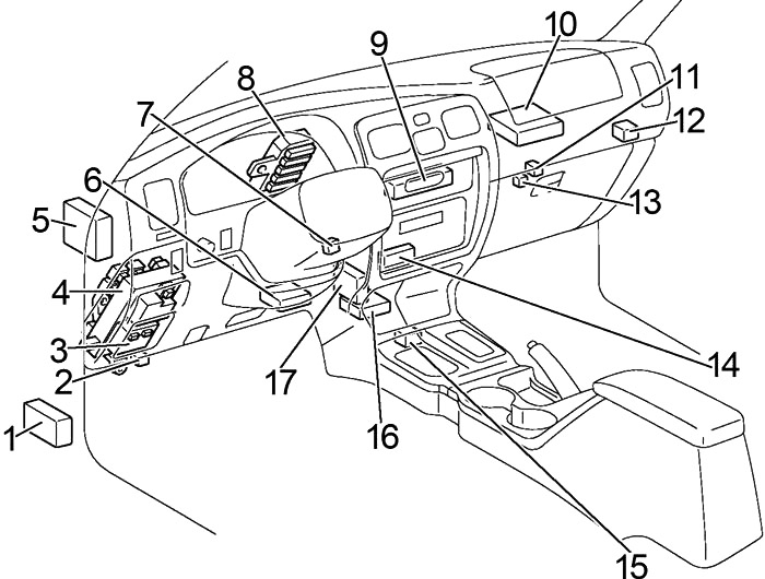
- 4WD ECU
- Circuit Opening Relay (Fuel Pump)
- Body ECU
- Fuse Box
- VSC ECU
- Daytime Running Light Relay (Main)
- Transponder Key Amplifier
- Junction Block
- A/C Amplifier
- Engine Control Module
- Extra High-Speed Relay
- Daytime Running Light Relay №4
- A/C Magnetic Clutch Relay (Automatic Air Conditioning)
- Stereo Power Amplifier
- Shift Lock Control Computer
- Center Airbag Sensor Assembly
- Auto Antenna Control Relay
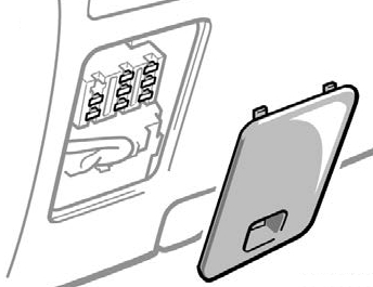
Passenger Compartment Fuse Box
The fuse panel is located behind the cover on the dashboard.
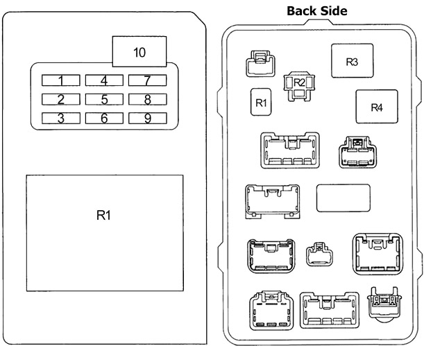
| № | Fuse | A | Designation |
|---|---|---|---|
| 1 | - | - | - |
| 2 | ACC | 15 | Car audio system, power antenna, clock, power rear view mirror control |
| 3 | ECU-B | 7.5 | SRS airbag warning light |
| 4 | 4WD | 20 | A.D.D. control system, four−wheel drive control system, rear differential lock system |
| 5 | TURN | 10 | Turn signal lights, emergency flashers |
| 6 | GAUGE | 10 | Gauges and meters, back window defogger, daytime running light system, air conditioning system, electric moon roof |
| 7 | ECU-IG | 10 | Cruise control system, anti−lock brake system, electronically controlled automatic transmission system, power antenna |
| 8 | WIPER | 20 | Windshield wipers and washer, back window wiper |
| 9 | IGN | 7.5 | SRS airbag system, multiport fuel injection system / sequential multiport fuel injection system, discharge warning light |
| 10 | POWER | 30 | Power window, power back window, electric moon roof |
| R1 | Integration relay | ||
| R1 | Horn | ||
| R2 | Turn signal flasher | ||
| R3 | Power relay | ||
| R4 | Rear window defogger | ||
Advertisements
Engine Compartment
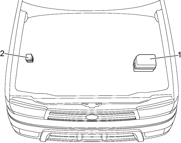
- Fuse Box
- Relay Box
Engine Compartment Fuse Box
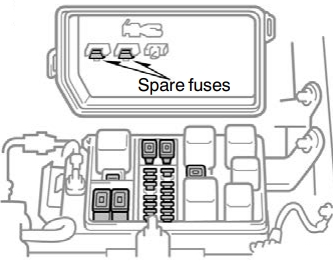
Diagram (Type 1)
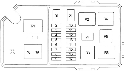
| № | Fuse | A | Designation |
|---|---|---|---|
| 1 | PWR OUTLET | 15 | Power outlet |
| 2 | DEFOG | 15 | Rear window defogger |
| 3 | STOP | 10 | Stop lights, high−mounted stoplight |
| 4 | ALT-S | 7.5 | Charging system |
| 5 | - | - | - |
| 6 | OBD | 7.5 | On-board diagnosis system |
| 7 | EFI | 15 | Multiport fuel injection system/sequential multiport fuel injection system |
| 8 | HORN | 15 | Horn, emergency flashers |
| 9 | DOME | 15 | Interior lights, personal lights, luggage compartment light, clock, car audio system |
| 10 | TAIL | 10 | Tail lights, parking lights, license plate lights |
| 11 | STA | 7.5 | Starting system |
| 12 | A.C | 10 | Air conditioning control system |
| 13 | RR HTR | 10 | Rear air conditioning control system |
| 14 | HEAD (RH) | 10 | Right-hand headlight |
| HEAD (HI RH) | 10 | with DRL: Right-hand headlight (high beam) | |
| 15 | HEAD (LH) | 10 | Left-hand headlight |
| HEAD (HI LH) | 10 | with DRL: Left-hand headlight (high beam) | |
| 16 | HEAD (LO RH) | 10 | with DRL: Right-hand headlight (low beam) |
| 17 | HEAD (LO LH) | 10 | with DRL: Left-hand headlight (low beam) |
| 18 | ABS | 60 | Anti-lock brake system |
| 19 | ALT | 100 | Charging system |
| 20 | HEATER | 50 | Air conditioning system, "A.C.” fuse |
| 21 | AM1 | 40 | Starting system |
| 22 | AM2 | 30 | Starting system, "IGN” fuse |
| R1 | Dimmer | ||
| R2 | Tail lights (TAIL) | ||
| R3 | Headlights (HEAD) | ||
| R4 | Heater | ||
| R5 | Starter | ||
| R6 | Engine control unit (EFI) | ||
Advertisements
Diagram (Type 2)
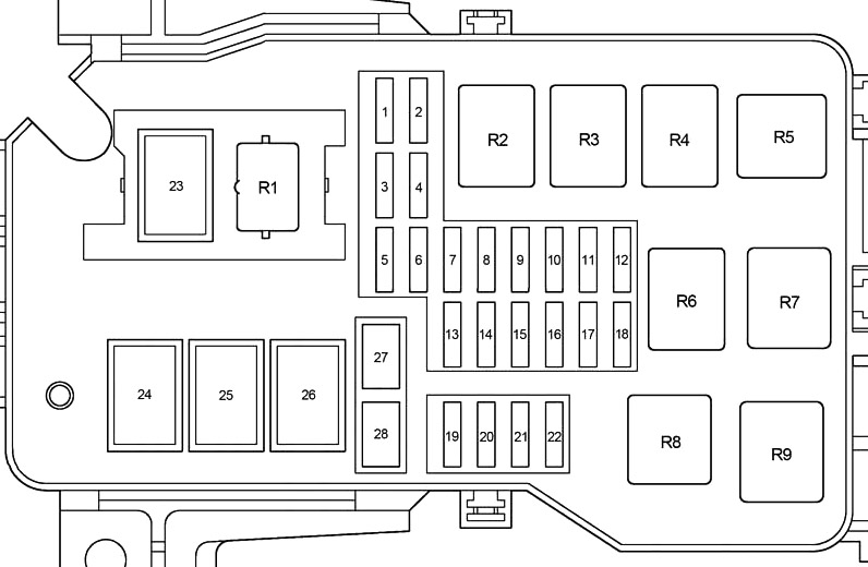
| № | Fuse | A | Designation |
|---|---|---|---|
| 1 | - | - | - |
| 2 | PWR OUTLET | 15 | Power outlet |
| 3 | DRL | 7.5 | Daytime running light system |
| 4 | - | - | - |
| 5 | TAIL | 10 | Tail lights, parking lights, license plate lights |
| 6 | A.C | 10 | Air conditioning control system |
| 7 | HEAD (LO RH) | 10 | with DRL: Right-hand headlight (low beam) |
| HEAD (RH) | 10 | Right-hand headlight | |
| 8 | HEAD (LO LH) | 10 | with DRL: Left-hand headlight (low beam) |
| HEAD (LH) | 10 | Left-hand headlight | |
| 9 | HEAD (HI RH) | 10 | with DRL: Right−hand headlight (high beam) |
| 10 | HEAD (HI LH) | 10 | with DRL: Left−hand headlight (high beam) |
| 11 | - | - | - |
| 12 | STA | 7.5 | Starting system |
| 13 | - | - | Not used |
| 14 | DEFOG | 15 | Back window defogger |
| 15 | STOP | 10 | Stop lights, high-mounted stoplight |
| 16 | RR HTR | 10 | Rear air conditioning control system |
| 17 | ALT−S | 7.5 | Charging system |
| 18 | - | - | - |
| 19 | DOME | 15 | Interior lights, personal lights, luggage compartment light, clock, car audio system |
| 20 | OBD | 7.5 | On-board diagnosis system |
| 21 | HORN | 15 | Emergency flashers, horns |
| 22 | EFI | 15 | Multiport fuel injection system/sequential multiport fuel injection system |
| 23 | - | - | - |
| 24 | HEATER | 40 | Air conditioning system, "A.C" fuse |
| 25 | ABS | 60 | Anti−lock brake system |
| 26 | ALT | 100 | Charging system |
| 27 | AM1 | 40 | Starting system |
| 28 | AM2 | 30 | Starting system, "IGN" fuse |
| R1 | Dimmer | ||
| R2 | Engine control unit (EFI) | ||
| R3 | - | ||
| R4 | Power outlet | ||
| R5 | - | ||
| R6 | Taillights | ||
| R7 | Starter | ||
| R8 | Headlight | ||
| R9 | Heater | ||
Relay Box
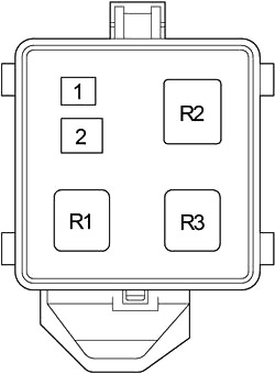
| № | Fuse | A | Designation |
|---|---|---|---|
| 1 | - | - | - |
| 2 | - | - | - |
| R1 | Traction control system (TRC MTR) | ||
| R2 | Anti-lock brake system (ABS SOL) | ||
| R3 | Anti-lock brake system (ABS MTR) | ||
Advertisements