
Advertisements
Fuse box diagram (fuse layout), location, and assignment of fuses and relays Suzuki / Maruti Alto 800, K10 (2012, 2013, 2014, 2015, 2016, 2017).

Checking and Replacing Fuses
The fuses are designed to melt during an overload to prevent damage to the wiring harness and electrical equipment. If any lights, accessories or other electrical controls do not operate, inspect the corresponding fuse. Look through the clear side of the fuse to see if the metal wire inside is separated. If it is, the fuse is blown and should be replaced.
Notice
- Before replacing the fuses, turn the ignition switch to the “LOCK” position and turn off all electrical accessories.
- Always be sure to replace a blown fuse with a fuse of the correct amperage. Using a fuse with a higher amperage rating can cause severe wire damage and could start a fire.
- Never use a substitute such as a wire even for a temporary repair, or extensive electrical damage, and a fire can result.
- We recommend always carrying replacement fuses in the vehicle.
- If the main fuse or a primary fuse blows, be sure to have your vehicle inspected by an authorised Suzuki workshop.
- If you replace a fuse and the new one blows in a short period of time, you may have a major electrical problem. Have your vehicle inspected immediately by your authorised Suzuki workshop.
Your vehicle has three types of fuses, as described below:
- Main fuse: The main fuse takes current directly from the battery.
- Primary fuses: These fuses are between the main fuse and individual fuses, and are for electrical load groups.
- Individual fuses: These fuses are for individual electrical circuits. To remove a fuse, use the fuse puller provided in the fuse box.
Passenger Compartment Fuse Box Diagram
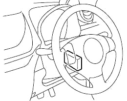
The fuse box is located under the driver’s side of the dashboard.
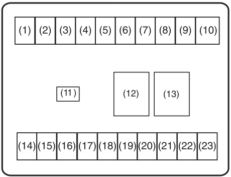
| № | A | Function/component |
|---|---|---|
| 1 | 10 | IG2 SIG |
| 2 | 15 | Wipers |
| 3 | - | Not used |
| 4 | 7.5 | Automated Manual Transaxle 2 (if equipped) |
| 5 | 30 | Blower motor |
| 6 | 10 | Stop light |
| 7 | 10 | Tail light |
| 8 | 15 | Audio |
| 9 | 20 | Door lock |
| 10 | - | Not used |
| 11 | 15 | Accessory |
| 12 | - | Not used |
| 13 | 30 | Power window |
| 14 | 15 | Ignition switch |
| 15 | 10 | Turn signal light |
| 16 | 10 | Meter |
| 17 | 7.5 | Air bag |
| 18 | 7.5 | IG1 SIG |
| 19 | - | Not used |
| 20 | - | Not used |
| 21 | 30 | Power steering |
| 22 | 30 | ST SIG |
| 23 | 15 | Horn/Hazard |
Advertisements
Engine Compartment Fuse Box Diagram
The main fuse, primary fuses, and some of the individual fuses are located in the engine compartment. If the main fuse blows, no electrical component will function. If a primary fuse blows, no electrical component in the corresponding load group will function.
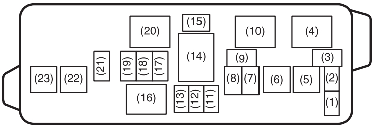
To remove a fuse, use the fuse puller provided in the back of the fuse box cover. The amperage of each fuse is shown in the back of the fuse box cover.
| № | A | Function/component |
|---|---|---|
| 1 | - | Not used |
| 2 | - | Not used |
| 3 | 10 | Font fog light |
| 5 | 50 | Ignition switch |
| 6 | 50 | Battery 1 |
| 7 | 15 | Headlight (left) |
| 8 | 15 | Headlight (right) |
| 9 | 7.5 | CNG (if equipped) |
| 11 | - | Not used |
| 12 | - | Not used |
| 13 | - | Not used |
| 14 | 80 | All electric load |
| 15 | - | Not used |
| 17 | 30 | Radiator fan |
| 18 | 15 | Fuel injection |
| 19 | 10 | A/c compressor |
| 21 | 7.5 | Automated Manual Transaxle (if equipped) |
| CNG Valve (if equipped) | ||
| 22 | 40 | Automated Manual Transaxle pump (if equipped) |
| 23 | 30 | Battery 2 |
| 4 | A/c compressor relay | |
| 10 | Radiator fan relay | |
| 16 | Main relay | |
| 20 | Fuel pump relay | |
Advertisements