
Advertisements
Fuse box diagram (fuse layout), location, and assignment of fuses and relays Suzuki Kizashi (2009, 2010, 2011, 2012, 2013, 2014).

Checking and Replacing Fuses
The fuses are designed to melt during an overload to prevent damage to the wiring harness and electrical equipment. If any lights, accessories or other electrical controls do not operate, inspect the corresponding fuse. Look through the clear side of the fuse to see if the metal wire inside is separated. If it is, the fuse is blown and should be replaced.
Notice:
- Before replacing the fuses, turn the ignition switch to the “LOCK” position and turn off all electrical accessories.
- Always be sure to replace a blown fuse with a fuse of the correct amperage. Using a fuse with a higher amperage rating can cause severe wire damage and could start a fire.
- Never use a substitute such as aluminum foil or wire to replace a blown fuse.
- We recommend always carrying replacement fuses in the vehicle.
- If the main fuse or a primary fuse blows, be sure to have your vehicle inspected by an authorised Suzuki workshop.
- If you replace a fuse and the new one blows in a short period of time, you may have a major electrical problem. Have your vehicle inspected immediately by your SUZUKI dealer.
Instrument Panel Fuse Boxes
Driver’s side
The fuses are located under the driver’s side of the dashboard. To access these fuses, pull the dashboard undercover to release its clip engagements and then remove the undercover. The amperage of each fuse is shown on the top of the dashboard undercover.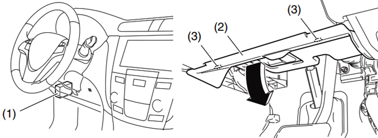
Fuse Box Diagram
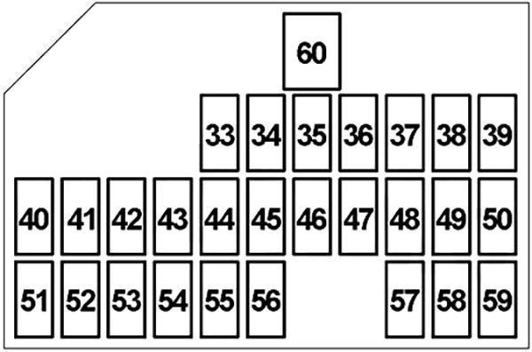
| № | A | Protected Component |
|---|---|---|
| 33 | 15 | Windshield Washer Motor, Body Control Module (BCM) |
| 34 | 20 | Seat Heater |
| 35 | 25 | Windshield Wiper Motor, Windshield Wiper Relay, Windshield Hi/Lo Relay |
| 36 | 7.5 | Rain & Light Sensor, Rear Defogger Relay, Keyless Start Control Module, Sunroof Unit, Auto-Dimming Rearview Mirror, Blower Motor Relay, Headlight Washer Control Module |
| 37 | 15 | Generator, Ignition Coil #1-#4, Engine Control Module (ECM) |
| 38 | 15 | Accessory Socket No.2 |
| 39 | 15 | Accessory Socket No.1, Power Mirror Switch, Keyless Start Control Module, Power Seat Control Module, Audio, Navigation |
| 40 | - | - |
| 41 | - | - |
| 42 | 10 | Electronic Stability Program (ESP) Control Module, Steering Angle Sensor |
| 43 | 7.5 | Brake Light Switch, Cruise Control |
| 44 | 7.5 | Continuously Variable Transmission (CVT) Relay, Four-Wheel Drive (4WD) Control Module, P/S Control Module |
| 45 | 7.5 | - |
| 46 | 7.5 | Auto A/C Panel, Body Control Module (BCM), Keyless Start Control Module, Combination Meter |
| 47 | 10 | Transaxle Range Sensor, Body Control Module (BCM), Parking Sensor System Control Module, ESP OFF / Parking Sensor OFF Switch, Power Seat Control Module, Headlight Auto Leveling Control Module, HVAC Control Module, Seat Heater, Back-Up Light Switch |
| 48 | 10 | Air Bag Module (SDM) |
| 49 | 15 | Keyless Start Control Module, Steering Lock |
| 50 | 7.5 | Keyless Start Control Module, Body Control Module (BCM) |
| 51 | 20 | Sunroof Unit |
| 52 | 7.5 | Rear Fog Light Relay |
| 53 | 10 | Tail Light Relay |
| 54 | 10 | Brake Light Switch |
| 55 | 10 | Hazard Flasher, Body Control Module (BCM) |
| 56 | 20 | Power Window Master Switch, Front Power Window Motor (Driver Side), Power Window Sub Switch, Front Power Window Motor (Passenger Side) |
| 57 | 15 | Audio, Navigation |
| 58 | 10 | Engine Control Module (ECM), Body Control Module (BCM), Keyless Start Control Module, Engine Switch, Auto A/C Panel, Data Link Connector (DLC), Combination Meter, Console, Rear Dome Light, Vanity Light, Courtesy Light, Trunk Light, Glove Box Light, Foot Light, HVAC Control Module |
| 59 | 20 | Door Lock, Body Control Module (BCM), Fuel Lid Motor Relay No.1&2 |
| 60 | 30 | Power Window Master Switch, Rear Power Window Sub Switch |
| R1 | Ignition (IG2) | |
| R2 | Ignition (IG1) | |
| R3 | Accessory | |
| R4 | Tail Light | |
Passenger’s side
The fuses are also located under the passenger’s side of the dashboard. Remove the two screws and dashboard under cover.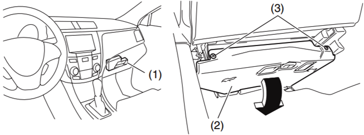
Fuse Box Diagram
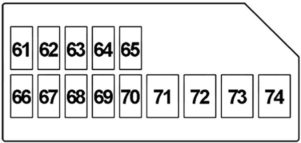
| № | A | Protected Component |
|---|---|---|
| 61 | 20 | Rear Power Window (Right) |
| 62 | 20 | Rear Power Window (Left) |
| 63 | 20 | Power Window Master Switch, Power Window Sub Switch, Front Power Window Motor |
| 64 | 15 | Four-Wheel Drive (4WD) Control Module |
| 65 | 20 | Battery Fan |
| 66 | - | - |
| 67 | - | - |
| 68 | - | - |
| 69 | - | - |
| 70 | - | - |
| 71 | 20 | Audio Amplifier |
| 72 | 30 | Right Seat (Power Seat Control Module, Lumbar Support Switch, Power Seat Sub Switch) |
| 73 | 30 | Left Seat (Power Seat Control Module, Lumbar Support Switch, Power Seat Sub Switch) |
| 74 | 30 | - |
Advertisements
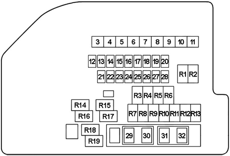
Engine Compartment Fuse Box Diagram
The main fuse, primary fuses, and some of the individual fuses are located in the engine compartment. To remove a fuse, use the fuse puller provided in the fuse box. The amperage of each fuse is shown in the back of the fuse box cover.
| № | A | Protected Component |
|---|---|---|
| 3 | 50 | Blower Motor Relay |
| 4 | 50 | Passenger Compartment Fuse Box No.2 (Power Window, Power Seat) |
| 5 | 50 | Passenger Compartment Fuse Box No.1 (Keyless Start Control Module) |
| 6 | 40 | Electronic Stability Program (ESP) Control Module |
| 7 | 40 | Passenger Compartment Fuse Box No.1 (Light) |
| 8 | 30 | Starting Motor Relay |
| 9 | 30 | Radiator Cooling Fan Relay No.1 |
| 10 | 30 | Radiator Cooling Fan Relay No.3 |
| 11 | 50 | Passenger Compartment Fuse Box No.1 (Ignition Switch) |
| 12 | 25 | Passenger Compartment Fuse Box No.1 (Back Up) |
| 13 | 25 | Electronic Stability Program (ESP) Control Module |
| 14 | 20 | Main Relay (Engine Control) |
| 15 | 7.5 | High Beam Relay, Low Beam Relay (Left & Right) |
| 16 | 30 | Headlight Washer Motor |
| 17 | 30 | Rear Defogger Relay |
| 18 | 15 | Throttle Actuator Control Relay |
| 19 | 15 | Mirror Heater Relay |
| 20 | 10 | A/C Compressor Relay |
| 21 | 15 | High Beam (Right) |
| 22 | 15 | High Beam (Left) |
| 23 | 15 | Low Beam (Right) or High Intensity Discharge (HID) Headlight (Right) |
| 24 | 15 | Low Beam (Left) or High Intensity Discharge (HID) Headlight (Left) |
| 25 | - | - |
| 26 | - | - |
| 27 | - | - |
| 28 | - | - |
| 29 | 15 | Horn |
| 30 | 15 | Heated Oxygen Sensor (HO2S) Relay |
| 31 | 20 | Front Fog Light Relay |
| 32 | 15 | Continuously Variable Transmission (CVT) Relay, Transmission Control Module (TCM) |
| R1 | Low Beam (Right) | |
| R2 | Low Beam (Left) | |
| R3 | A/C Compressor | |
| R4 | Rear Fog Light | |
| R5 | - | |
| R6 | High Beam | |
| R7 | Fuel Pump | |
| R8 | Starting Motor | |
| R9 | Windshield Wiper | |
| R10 | - | |
| R11 | Windshield Wiper Hi/Lo | |
| R12 | - | |
| R13 | Rear Defogger | |
| R14 | Throttle Actuator Control | |
| R15 | Radiator Cooling Fan No.1 | |
| R16 | Main (Engine Control) | |
| R17 | Radiator Cooling Fan No.3 | |
| R18 | Radiator Cooling Fan No.2 | |
| R19 | Mirror Heater | |
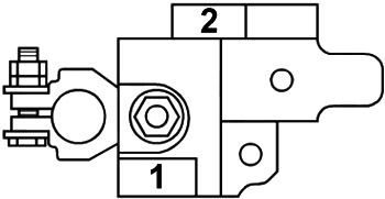
Fusible Link
| № | A | Protected Component |
|---|---|---|
| 1 | 120 | All Electric Circuit, Battery, Starting Motor, Generator |
| 2 | 80 | P/S Control Module |
Advertisements