
Advertisements
Fuse box diagram (fuse layout), location, and assignment of fuses Suzuki Ciaz (2014, 2015, 2016, 2017, 2018).
Checking and Replacing Fuses
The fuses are designed to melt during an overload to prevent damage to the wiring harness and electrical equipment. If any lights, accessories or other electrical controls do not operate, inspect the corresponding fuse. Look through the clear side of the fuse to see if the metal wire inside is separated. If it is, the fuse is blown and should be replaced.
Notice
- Before replacing the fuses, turn the ignition switch to the “LOCK” position and turn off all electrical accessories.
- Always be sure to replace a blown fuse with a fuse of the correct amperage. Using a fuse with a higher amperage rating can cause severe wire damage and could start a fire.
- Never use a substitute such as a wire even for a temporary repair, or extensive electrical damage, and a fire can result.
- We recommend always carrying replacement fuses in the vehicle.
- If the main fuse or a primary fuse blows, be sure to have your vehicle inspected by an authorised Suzuki workshop.
- If you replace a fuse and the new one blows in a short period of time, you may have a major electrical problem. Have your vehicle inspected immediately by your authorised Suzuki workshop.
Your vehicle has three types of fuses, as described below:
- Main fuse: The main fuse takes current directly from the battery.
- Primary fuses: These fuses are between the main fuse and individual fuses, and are for electrical load groups.
- Individual fuses: These fuses are for individual electrical circuits.
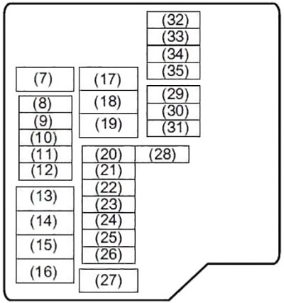
Instrument Panel Fuse Box Diagram
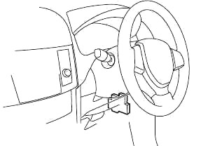
The fuse box is located under the driver’s side of the dashboard. Remove the fuse box cover by pushing in at both ends and pulling off the cover.
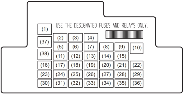
| № | A | Function/component |
|---|---|---|
| 1 | 20 | Power window |
| 2 | 20 | Steering lock |
| 3 | - | Not used |
| 4 | 20 | Rear defogger |
| 5 | - | Not used |
| 6 | - | Not used |
| 7 | - | Not used |
| 8 | 7.5 | Starting Signal |
| 9 | 15 | ACC-2 |
| 10 | 30 | Power window |
| 11 | 10 | Hazard |
| 12 | 7.5 | BCM |
| 13 | 15 | Ignition coil |
| 14 | 10 | ABS control module |
| 15 | 15 | ACC |
| 16 | 10 | A-STOP controller |
| 17 | 15 | Horn |
| 18 | 10 | Stop light |
| 19 | 10 | Air bag |
| 20 | 10 | Back-up light |
| 21 | 15 | WIP |
| 22 | 25 | Front wiper |
| 23 | 7.5 | Dome light |
| 24 | - | Not used |
| 25 | - | Not used |
| 26 | - | Not used |
| 27 | 7.5 | Ignition-1 signal |
| 28 | 15 | Radio 2 |
| 29 | 10 | ACC-3 |
| 30 | 15 | Radio |
| 31 | 10 | Tail lamp |
| 32 | 20 | D/L |
| 33 | 7.5 | Stop lamp sw / Clutch sw |
| 34 | 10 | Meter |
| 35 | 7.5 | Ignition-2 signal |
| 36 | - | Not used |
Advertisements
Engine Compartment Fuse Box Diagram
The main fuse, primary fuses, and some of the individual fuses are located in the engine compartment. If the main fuse blows, no electrical component will function. If a primary fuse blows, no electrical component in the corresponding load group will function.
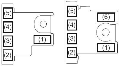
To remove a fuse, use the fuse puller provided in the fuse box. The amperage of each fuse is shown in the back of the fuse box cover.
| № | A | Function/component |
|---|---|---|
| 1 | 100 | FL1 (GAS) |
| 450 | FL1 (DIESEL) | |
| 2 | 100 | FL2 |
| 3 | 100 | FL3 |
| 4 | 50 | FL4 |
| 5 | 80 | FL5 |
| 6 | 100 | FL6 |
| 7 | 50 | Ignition switch -2 |
| 8 | 7.5 | ECM |
| 0 | 15 | Automatic transaxle relay |
| 10 | - | Not used |
| 11 | 10 | Air compressor |
| 12 | 15 | FI (GAS) |
| 13 | 30 | FI (DIESEL) |
| 14 | 60 | Power steering |
| 15 | 30 | Radiator tan |
| 16 | 30 | CDSR |
| 17 | 30 | Blower fen |
| 18 | 30 | Starting motor |
| 19 | 40 | ABS motor |
| 20 | 30 | B/U |
| 21 | 15 | Headlight Lo (Left) |
| 22 | 15 | Headlight Lo (Right) |
| 23 | 25 | ABS control module |
| 24 | 30 | DCDC |
| 25 | 20 | Front fog light |
| 26 | 25 | Headlight |
| 27 | 40 | Ignition switch |
| 28 | 7.5 | Starting Signal |
| 29 | 20 | INJ DRV (DIESEL) |
| 30 | 10 | FI 2 |
| 31 | 15 | F/P (DIESEL) |
| 32 | 15 | Headlight high (Left) |
| 33 | 15 | Headlight high (Right) |
| 34 | - | Not used |
| 35 | 7.5 | WIP SUB |
Advertisements