
Advertisements
Fuse box diagram (fuse layout), location, and assignment of fuses and relays Smart Fortwo / Forfour (A453, C453, W453) (2014, 2015, 2016, 2017).

Checking and Replacing Fuses
The fuses in your vehicle serve to close down faulty circuits. If a fuse blows, all the components on the circuit and their functions stop operating. A blown fuse can be identified by the melted metal strip inside it. Blown fuses must be replaced with fuses of the same rating, which you can recognize by the color and value.
Before replacing fuses:
- Set the parking brake.
- Make sure the gear selector lever is in park position P.
- Turn off all electrical accessories.
- Turn off the engine.
- Remove the key from the starter switch.
A blown fuse must be replaced by an appropriate spare fuse (recognizable by its color or the fuse rating given on the fuse) of the amperage recommended in the fuse chart.
- From the fuse chart determine which fuse belongs to the malfunctioning accessory or component.
- Remove the respective fuse.
- Replace the defective fuse with a new one of the same amperage.
If a newly inserted fuse also blows, have the cause traced and rectified at a qualified specialist workshop, e.g. an authorized Mercedes-Benz Center.
Notice
- Only use fuses approved by Smart with the specified amperage for the system in question and do not attempt to repair or bridge a blown fuse this may cause an overload leading to a fire, and/or cause damage to electrical components and/or systems. Contact a smart center if you encounter any electrical problems.
- Never use a fuse with a higher amperage rating, or any other object, in place of a fuse. This may cause extensive damage and possibly a fire.
- We recommend always carrying replacement fuses in the vehicle.
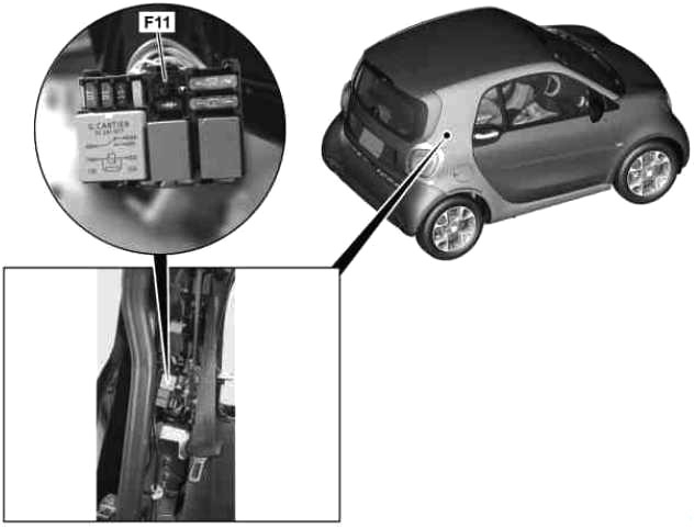
Fuse box in the glove compartment
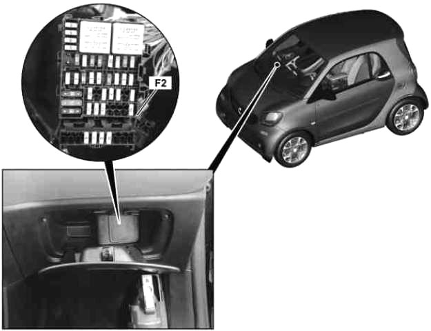
- Open the front-passenger door.
- Open the glove box.
- To open: open cover.
- Replace the defective fuse.
- To close: insert and fold in cover until it engages.
- Close the glove box.
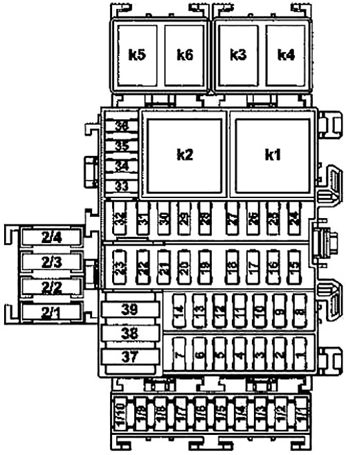
| № | Fused function | A |
|---|---|---|
| 1 | Rear roof rack electrical connection | 20 |
| 2 | - | - |
| 3 | - | - |
| 4 | - | - |
| 5 | Driver-side SAM control unit | 25 |
| 6 | Driver-side SAM control unit | 25 |
| 7 | Driver-side SAM control unit | 25 |
| 8 | Center SAM control unit | 15 |
| Radio | ||
| Radio over connector sleeve for terminal 15 R | ||
| 9 | - | - |
| 10 | Horn | 15 |
| 11 | Battery sensor and driver-side SAM control unit | 5 |
| 12 | Front cigarette lighter with ashtray illumination | 15 |
| 13 | - | - |
| 14 | Automatic transmission protected through connector sleeve for circuit 30 | 20 |
| Diagnostic connector | ||
| Valid for electric vehicle: | ||
| Fused circuit 30 connector sleeve | ||
| Diagnostic connector | ||
| 15 | Supply for fused circuit 30 connector sleeve | 15 |
| 16 | Motor electronics protected through connector sleeve for circuit 30 | 5 |
| Valid for electric vehicle: Supply for fused circuit 30 connector sleeve | ||
| 17 | Supply protected through connector sleeve for circuit 30 | 15 |
| 18 | Brake lights switch | 10 |
| 19 | Outside mirror adjustment switch | 5 |
| 20 | Transponder coil | 3 |
| Electronic Stability Program control unit and brake light switch | ||
| Protected through connector sleeve for circuit 30 | ||
| 21 | Light functions protected through connector sleeve for circuit 30 | 10 |
| 22 | Steering wheel angle sensor | 5 |
| Dual-clutch transmission control unit | ||
| 23 | - | - |
| 24 | Center SAM control unit | 15 |
| 25 | Center SAM control unit | 10 |
| 26 | Center SAM control unit | 15 |
| 27 | Center SAM control unit | 20 |
| 28 | Driver-side SAM control unit | 10 |
| 29 | Driver-side SAM control unit | 10 |
| 30 | Combination switch | 15 |
| Alarm siren | ||
| Supply for fused circuit 30 connector sleeve (valid for electric vehicle) | ||
| 31 | Instrument cluster and additional instruments | 10 |
| 32 | - | - |
| 33 | Supplemental Restraint System control unit | 5 |
| 34 | Combination switch | 5 |
| 35 | Electrical power steering control unit | 5 |
| 36 | Center SAM control unit | 5 |
| 37 | Driver-side SAM control unit | 30 |
| 38 | Air conditioning power supply solenoid switch | 40 |
| 39 | Starter | 30 |
| Through starter relay | ||
| 39 | Valid for electric vehicle: Blower motor | 40 |
| 1/1 | Valid for electric vehicle: Electric vehicle circuit 30 connector sleeve supply | 10 |
| 1/2 | Valid for electric vehicle: | - |
| Brake booster vacuum pump control unit | ||
| Power electronics control unit | ||
| 1/3 | - | - |
| 1/4 | Sound system amplifier control unit | 20 |
| 1/5 | Dual clutch transmission control unit | 5 |
| Valid for electric vehicle: Electric drive control unit | ||
| 1/6 | Left front power window motor and right front power window motor | 25 |
| 1/7 | Left electrically adjustable and heated outside mirror and right electrically adjustable and heated outside mirror | 5 |
| 1/8 | Valid for electric vehicle: | 25 |
| Front passenger seat heater control unit | ||
| Driver seat heater control unit | ||
| 1/9 | - | - |
| 1/10 | Valid for electric vehicle: Steering wheel heater relay | - |
| 2/1 | Supply for soft top control drive unit | 20 |
| 2/2 | Supply for soft top control drive unit | 20 |
| 2/3 | - | - |
| 2/4 | - | - |
| K1 | Heated rear window/outside mirrors relay | |
| K2 | Front power window relay | |
| K3 | Sliding roof relay | |
| K4 | Front headlamps relay | |
| K5 | Starter relay | |
| K6 | Fanfare horn relay | |
| K7 | Valid for electric vehicle: Steering wheel heater relay | |
Advertisements
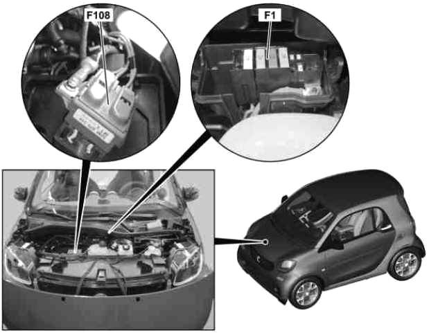
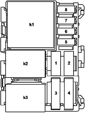
Fuse box in the front area
| № | Fused function | A |
|---|---|---|
| 1 | Heated rear window over relay for heated rear window/outside mirrors | 30 |
| 2 | Front passenger seat heater control unit | 30 |
| Driver seat heater control unit | ||
| Valid for electric vehicle: Brake booster vacuum pump control unit | ||
| 3 | Supply for Electronic Stability Program control unit | 25 |
| 4 | Valid for electric vehicle: - | 40 |
| Electrical fuse 1 and electrical fuse 2 | ||
| Sliding roof relay | 25 | |
| 5 | Supply for internal combustion engine fuse and relay module | 60 |
| 6 | Dual clutch transmission control unit | 50 |
| Protected through connector sleeve for circuit 30 | ||
| Valid for electric vehicle: Vehicle interior fuse and relay module supply | 40 | |
| 7 | Fan motor | 30 |
| Over fan relay | ||
| Fan solenoid switch | 30 | |
| ICE combustion engine cooling | ||
| 8 | - | - |
| 9 | Valid for USA:Secondary air injection pump | 60 |
| Valid for electric vehicle: | ||
| Heater for high-voltage battery | ||
| Over heater relay for high-voltage battery | ||
| K1 | Fan relay | |
Battery clamp fuses
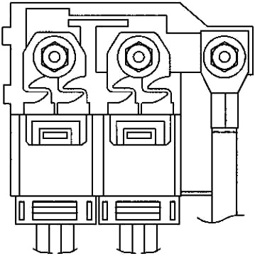
| № | Fused function | A |
|---|---|---|
| F1 | Electrical fuse 3A (F108f3A) and electrical fuse 3B (F108f3B) | 200 |
| Valid for electric vehicle: | ||
| Power supply fuse and relay module (F1) | ||
| DC/DC converter control unit | ||
| F2A | Vehicle interior fuse and relay module supply (F2) | 70 |
| Protected through connector sleeve for circuit 30 | ||
| Connector sleeve for circuit 30 | ||
| F2B | Electrical power steering control unit | 60 |
| F3A | Vehicle interior fuse and relay module supply (F2) | 70 |
| Ignition lock | ||
| Protected through connector sleeve for circuit 30 | ||
| Connector sleeve for circuit 30 | ||
| F3B | Electronic Stability Program control unit | 50 |
Advertisements
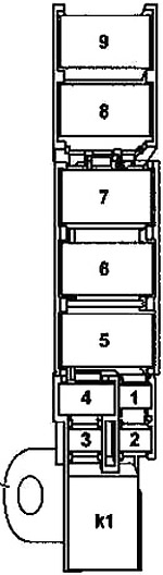
Power supply fuse and relay module
| № | Fused function | A |
|---|---|---|
| 1 | Internal combustion engine relay module | Diode |
| Valid for electric vehicle: - | ||
| 2 | Valid for USA: Supply for vacuum pump relay | Diode |
| Valid for electric vehicle: | 15 | |
| Transmission mode recognition sensor | ||
| Electric drive control unit | ||
| 3 | Fuel pump with fill level sensor and temperature sensor | 20 |
| Valid for electric vehicle: Electric vehicle drive motor fan relay | 40 | |
| 4 | Supply for fused circuit 30 connector sleeve | 25 |
| Valid for electric vehicle: Battery cooling system coolant pumps relay | 30 | |
| 5 | Supply for connector sleeves for circuit 87 | 15 |
| Valid for electric vehicle: Battery cooling system coolant pump | 15 | |
| 6 | Refrigerant compressor relay | 15 |
| Valid for electric vehicle: | 5 | |
| Battery management system control unit | ||
| Electric drive control unit | ||
| 7 | Fan | 10 |
| Through fan relay | ||
| Valid for electric vehicle: Power electronics control unit power supply connector sleeve supply | 20 | |
| 8 | Dual clutch transmission control unit | 10 |
| Valid for electric vehicle: Circuit 87 supply connector sleeve | 15 | |
| K1 | Engine function circuit 87 relay | |
| K2 | Fan relay | |
| K3 | Ignition coils/fuel pump actuation relay | |
| K4 | Valid for electric vehicle: Battery cooling system coolant pumps relay | |
Advertisements