
Advertisements
Fuse box diagram (fuse layout), location, and assignment of fuses and relays Smart Forfour (W454) (2004, 2005, 2006).
Checking and Replacing Fuses
The electrical fuses in your vehicle serve to switch off malfunctioning power circuits. If a fuse is blown, the components and systems secured by that fuse will stop operating. A blown fuse can be identified by the melted metal strip inside it.
Before replacing fuses:
- Set the parking brake.
- Make sure the gear selector lever is in park position P.
- Turn off all electrical accessories.
- Turn off the engine.
- Remove the key from the starter switch.
A blown fuse must be replaced by an appropriate spare fuse (recognizable by its color or the fuse rating given on the fuse) of the amperage recommended in the fuse chart.
- From the fuse chart determine which fuse belongs to the malfunctioning accessory or component.
- Remove the respective fuse.
- Replace the defective fuse with a new one of the same amperage.
If a newly inserted fuse blows again, have the cause determined and rectified at an authorized Smart center.
Notice
- Only use fuses approved by Smart with the specified amperage for the system in question and do not attempt to repair or bridge a blown fuse this may cause an overload leading to a fire, and/or cause damage to electrical components and/or systems. Contact a smart center if you encounter any electrical problems.
- Never use a fuse with a higher amperage rating, or any other object, in place of a fuse. This may cause extensive damage and possibly a fire.
- We recommend always carrying replacement fuses in the vehicle.
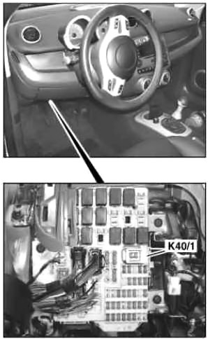
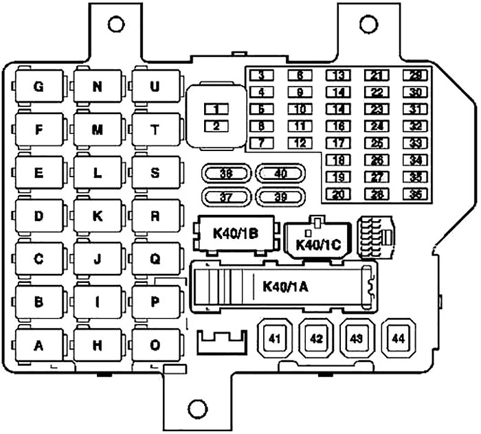
Instrument Panel Fuse Box Diagram
The fuse box is located on the driver’s side below the dashboard.
Advertisements
| № | Fused function | A |
|---|---|---|
| 1 | Interior illumination | 10 |
| Upper control panel control unit | ||
| Left SAM control unit | ||
| Rain sensor/light sensor | ||
| Instrument cluster | ||
| Combination switch | ||
| Central gateway control unit | ||
| 2 | Left SAM control unit | 10 |
| 3 | Left standing lamp and taillamp | 7.5 |
| 4 | Right parking light and taillamp | 7.5 |
| 5 | Front wiper | 20 |
| 6 | Vacant | - |
| 7 | Heated outside mirror | 7.5 |
| 8 | Right high beam | 10 |
| 9 | Left high beam | 10 |
| 10 | Horn | 10 |
| 11 | Fuel pump | 15 |
| 12 | ENGINE 122.9, 134.9, 135.9: | 20 |
| Motor electronics control unit | ||
| Motor relay | ||
| Throttle valve relay | ||
| 13 | Trailer hitch socket (13-pin) circuit 30 | 15 |
| 14 | Glass sliding roof | 20 |
| 15 | Rear window wiper motor | 15 |
| 16 | Cigarette lighter | 15 |
| 17 | Rear fog lamp | 7.5 |
| 18 | Outside mirror adjustment | 7.5 |
| 19 | ENGINE 639.9: | 15 |
| EDG control unit | ||
| 20 | ENGINE 639.9: | 7.5 |
| EDG control unit | ||
| Fuel pump relay 2 | ||
| Motor relay | ||
| 21 | Right low beam | 10 |
| 22 | Left low beam, headlamp range adjustment | 10 |
| 23 | Front fog lamp | 10/15 |
| 24 | Diagnostic socket, central locking (up to model year 04) | 15 |
| 25 | Trailer hitch socket (13-pin) circuit 15 | 15 |
| 26 | Turn signal lights | 10 |
| 27 | Radio | 15 |
| 28 | Anti-theft alarm system | 10 |
| 29 | Manual transmission | 20 |
| 30 | Diagnostic socket, central locking (as of model year 05) | 15 |
| 31 | Brake lights | 15 |
| Stop lamp switch (4-pin) | ||
| 32 | AAC [KLA] control and operating unit | 7.5 |
| 33 | ESP control unit | 7.5 |
| Steering assist control unit | ||
| Restraint systems control unit | ||
| 34 | ENGINE 122.9, 134.9, 135.9: | 10 |
| Ignition coils | ||
| 35 | EDG control unit | 7.5 |
| Fuel pump relay 1 | ||
| 36 | Reversing lights | 7.5 |
| 37 | Rear window heater | 30 |
| 38 | Heated seats | 30 |
| 39 | ENGINE 639.9: | 30 |
| EDG control unit | ||
| 40 | Heater blower | 40 |
| 41 | Ignition/starter switch | 40 |
| 42 | Power windows | 40 |
| Headlamp cleaning system pump | ||
| 43 | Engine coolant fan motor | 40 |
| 44 | Electronic selector lever module control unit (with transmission 717.474, 717.475) | 40 |
| A | Power window relay | |
| B | Horn relay | |
| C | Fuel pump 2 relay | |
| D | Rear fog lamps relay | |
| E | Starter relay | |
| F | Gasoline/diesel engine relay | |
| G | Preexcitation alternator | |
| H | Fan stage 1 relay | |
| I | Fog lamp relay | |
| J | Heater relay | |
| K | Fuel pump 1 relay | |
| L | Transmission relay | |
| M | Trailer hitch bridge | |
| N | Free (backup relay) | |
| O | Fan stage 2 relay | |
| P | Headlamp cleaning system relay | |
| Q | Rear window defroster relay | |
| R | Heated seats bridge | |
| S | Low beam relay | |
| T | High beam relay | |
| U | Throttle valve relay (only with engine 134.910, 135.930/950) | |
Advertisements