
Advertisements
Fuse box diagram (fuse layout), location, and assignment of fuses Skoda Yeti (2009, 2010, 2011, 2012, 2013, 2014, 2015, 2016, 2017).
Checking and Replacing Fuses
Individual electrical circuits are protected by fuses.
- Before replacing a fuse, switch off the ignition and the appropriate consumer.
- Find out which fuse belongs to the component that is not operating.
- A blown fuse is recognizable by the molten metal strip. Replace the faulty fuse with a new one of the same amperage
- If a new fuse burns through again, consult a specialist immediately.
Notice
- Never “repair” fuses and also do not replace them with a fuse of a higher amperage – risk of fire! This may also cause damage at another part of the electrical system.
- Have the electrical system checked as quickly as possible by a ŠKODA specialist garage if a newly inserted fuse blows again after a short time.
- We recommend always carrying replacement fuses in the vehicle.
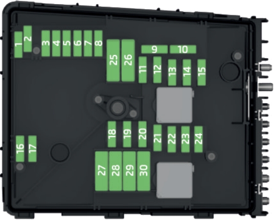
Passenger Compartment Fuse Box
The fuses are located on the left side of the dash panel behind a cover.
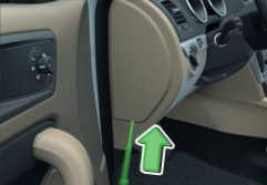
- Insert a screwdriver into the opening in the cover in the direction of the arrow.
- Remove the cover of the fuse box and remove it.
- Remove the plastic clip from the holder in the fuse box cover in the dash panel.
- Place the clip on the respective fuse and pull this fuse out.
- Insert a new fuse.
- Replace the bracket at the original position.
- Re-insert the cover of the fuse box.
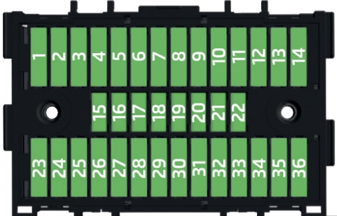
| № | Power consumer |
|---|---|
| 1 | Heating of the gearbox vent (diesel engine) |
| Automatic gearbox | |
| 2 | Towing hitch - left light |
| 3 | Trailer device - electrical outlet |
| 4 | Instrument cluster control lever under the steering wheel, camera |
| 5 | Air blower for heating, radiator fan, air conditioning system, Climatronic |
| 6 | Rear window wiper |
| 7 | Emergency call |
| 8 | Towing hitch - right light |
| 9 | Interior lighting, rear fog light |
| 10 | Rain sensor, light switch, diagnostic socket |
| 11 | Left side front headlight |
| 12 | Right side front headlight |
| 13 | Radio |
| 14 | Central control system, engine management system |
| 15 | Light switch |
| 16 | All-wheel drive |
| 17 | KESSY, steering lock |
| 18 | Diagnostic connector, engine control system, brake sensor, four-wheel drive, START-STOP |
| 19 | ABS, ESP, switch for tyre air pressure control, parking aid, switch for OFF ROAD mode, START STOP button |
| 20 | Airbag |
| 21 | Variable Service Interval - WIV, reversing lamps, dimmable mirrors, pressure sensor, telephone preparation, air mass meter, headlamp levelling and swivelling headlights |
| 22 | Instrument cluster, electromechanical power steering, databus |
| 23 | Central locking, boot lid |
| 24 | Electric windows - Rear |
| 25 | Rear window heater, auxiliary heating and ventilation |
| 26 | Power socket in the boot |
| 27 | Panoramic tilt / slide sunroof, electric operation of sun blinds |
| 28 | Fuel pump, injectors, AdBlue heating |
| 29 | Electric windows - front, outside mirror - Heating, fold-in function, Adjusting the mirror surface |
| 30 | 12 volt power outlet - front and rear |
| 31 | Headlight cleaning system |
| 32 | Heated front seats |
| 33 | Heating, air conditioning, Climatronic, remote control for auxiliary heating |
| 34 | Car alarm, reserve horn |
| 35 | Automatic gearbox |
| 36 | Tow hitch |
Advertisements
Engine Compartment Fuse Box
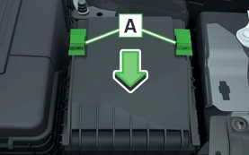
- Turn the securing bracket “A” in direction of the arrow. The symbol is displayed behind the catches.
- Remove the cover.
With some equipment, the battery cover must be opened before removing the cover for the fuse box.
| № | Power consumer |
|---|---|
| 1 | Not assigned |
| 2 | Automatic gearbox, AdBlue control system |
| 3 | Battery data module |
| 4 | ABS |
| 5 | Automatic gearbox |
| 6 | Not assigned |
| 7 | Power supply for terminal 15, starter |
| 8 | Radio, instrument cluster, telephone |
| 9 | Not assigned |
| 10 | Engine control system |
| 11 | Aux. heating and ventilation |
| 12 | Databus |
| 13 | Engine control system |
| 14 | Ignition |
| 15 | Lambda probe, fuel pump, glow plug system |
| 16 | Right headlight, right taillight |
| 17 | Horn |
| 18 | Music amplifier |
| 19 | Windscreen wipers |
| 20 | Control valve for fuel pressure, high pressure pump |
| 21 | Lambda probe |
| 22 | Clutch pedal switch, brake pedal switch |
| 23 | Coolant pump, loading pressure control valve, switchover valve for radiator, fuel pump |
| 24 | Active charcoal filter, exhaust gas recirculation valve, radiator fan |
| 25 | ABS |
| 26 | Left front headlight, left taillight |
| 27 | Glow plug system |
| 28 | Windscreen heater |
| 29 | Power to the internal fuse carrier (fuses no. 24,27,31,32), electrically adjustable seats |
| 30 | Terminal X |
Advertisements