
Advertisements
Fuse box diagram (fuse layout), location, and assignment of fuses and relays Scion xB (2004, 2005, 2006, 2007).
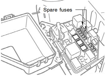
Checking and Replacing Fuses
If the headlights or other electrical components do not work, check the fuses. The fuse has blown if the filament inside it is broken. If any of the fuses are blown, they must be replaced.
Turn the ignition switch and inoperative component off. Pull the suspected fuse straight out and check it. Determine which fuse may be causing the problem. The lid of the fuse box shows the name of the circuit for each fuse. See below for the functions controlled by each circuit.
If you are not sure whether the fuse has blown, try replacing the suspected fuse with one that you know is good. If the fuse has blown, push a new fuse into the clip. Only install a fuse with the amperage rating designated on the fuse box lid.
If you cannot use one of the same amperage, use one that is lower, but as close to the rating as possible. If the amperage is lower than that specified, the fuse might blow out again but this does not indicate anything wrong. Be sure to get the correct fuse as soon as possible and return the substitute to its original clip.
Notice
- Always switch off the ignition system and the affected electrical circuit before replacing a fuse.
- Never use a fuse with a higher amperage rating, or any other object, in place of a fuse. This may cause extensive damage and possibly a fire.
- If the new fuse immediately blows out, there is a problem with the electrical system. Have your Scion dealer correct it as soon as possible.
Passenger Compartment
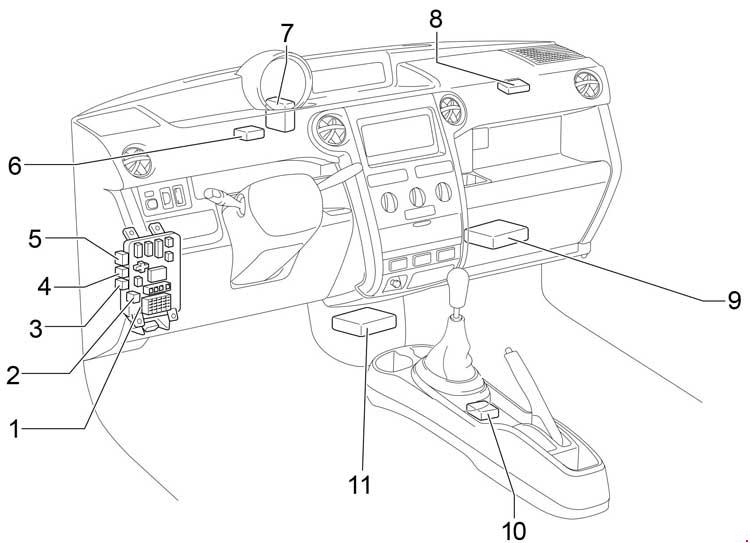
- Instrument Panel J/B
- Fuse Block
- Front Fog Light Relay
- Headlight Relay
- Rear Window Defogger Relay
- Door Control Receiver
- Door Lock Control Relay
- A/C Amplifier
- Engine Control Module
- Shift Lock Control SW
- Airbag Sensor Assembly
Instrument Panel Fuse Box Diagram
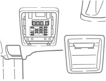
The fuse panel is located behind the cover underneath the left side of the dash panel.
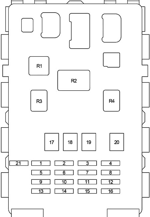
| № | Fuse | A | Designation |
|---|---|---|---|
| 1 | GAUGE | 10 | Back−up lights, charging system, air conditioning system, power window system, gauges of meters |
| 2 | - | - | Not used |
| 3 | D/L | 25 | Power door lock system |
| 4 | TAIL | 10 | Tail lights, parking lights, license plate lights |
| 5 | - | - | Not used |
| 6 | WIPER | 20 | Windshield wipers and washer |
| 7 | ECU−B | 7.5 | SRS airbag system |
| 8 | FOG | 15 | Front fog lights |
| 9 | ACC | 15 | Clock, cigarette lighter |
| 10 | ECU−IG | 7.5 | Anti−lock brake system, electric cooling fan |
| 11 | OBD | 7.5 | On−board diagnosis system |
| 12 | HAZ | 10 | Turn signal lights, emergency flashers |
| 13 | A.C | 7.5 | Air conditioning system |
| 14 | - | - | Not used |
| 15 | - | - | Not used |
| 16 | STOP | 10 | Stop lights, high mounted stop light, anti−lock brake system, shift lock system, multiport fuel injection system/sequential multiport fuel injection system |
| 17 | AM1 | 40 | "ACC”, "GAUGE”, "WIPER”, and "ECU−IG” fuses |
| 18 | POWER | 30 | Power windows |
| 19 | HTR | 40 | Air conditioning system |
| 20 | DEF | 30 | Rear window defogger system |
| 21 | I/UP | 7.5 | Rear window defogger system, multiport fuel injection system/ sequential multiport fuel injection system |
| R1 | Air conditioning system | ||
| R2 | Flasher | ||
| R3 | Power windows | ||
| R4 | Circuit Opening Relay | ||
Advertisements
Engine Compartment
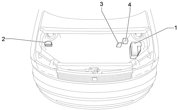
- Fuse Box
- Additional Relay Box
- Fusible Link Block
- Skid Control ECU with Actuator
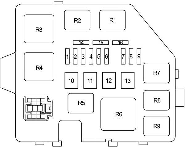
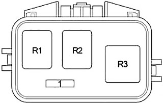
Engine Compartment Fuse Box Diagram
| № | Fuse | A | Designation |
|---|---|---|---|
| 1 | DOME | 15 | Clock, interior light, gauges of meters |
| 2 | EFI | 15 | Multiport fuel injection system/sequential multiport fuel injection system |
| 3 | HORN | 15 | Horn |
| 4 | AM2 | 15 | Starter system, SRS airbag system, multiport fuel injection system/sequential multiport fuel injection system, discharge warning system |
| 5 | ST | 30 | Starter system |
| 6 | - | - | Not used |
| 7 | H−LP LH | 10 | Left−hand headlight |
| H−LP LO LH | |||
| 8 | H−LP RH | 10 | Right−hand headlight |
| H−LP LO RH | |||
| 9 | A/C2 | 7.5 | Air conditioning system |
| 10 | - | - | Not used |
| 11 | RDI | 30 | Electric cooling fan |
| 12 | HTR SUB1 | 50 | Air conditioning system |
| 13 | ABS №1 | 40 | Anti−lock brake system |
| 14 | SPARE | 30 | Spare |
| 15 | SPARE | 15 | Spare |
| 16 | - | - | Not used |
| R1 | Electric cooling fan (№1) | ||
| R2 | Electric cooling fan (№2) | ||
| R3 | Starter | ||
| R4 | Not used | ||
| R5 | Not used | ||
| R6 | Heater (A/C) | ||
| R7 | EFI | ||
| R8 | Not used | ||
| R9 | Horn | ||
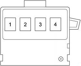
Fusible Link Block
It is on the battery “+” terminal.
| № | Fuse | A | Designation |
|---|---|---|---|
| 1 | - | - | Not used |
| 2 | MAIN | 60 | ABS, TRAC and VSC |
| Charging | |||
| Combination Meter | |||
| Electronically Controlled Transmission and A/T Indicator | |||
| Engine Control | |||
| Seat Belt Warning (From Dec. 2005 Production) | |||
| SRS | |||
| Starting and Ignition | |||
| 3 | ALT | 120 | ABS, TRAC and VSC |
| Charging | |||
| 4 | ABS | 60 | ABS, TRAC and VSC |
Additional Relay Box
| № | Fuse | A | Designation |
|---|---|---|---|
| 1 | - | - | Not used |
| R1 | Not used | ||
| R2 | ABS | ||
| R3 | ABS | ||
Advertisements