
Advertisements
Fuse box diagram (fuse layout), location, and assignment of fuses for Scion FR-S (2013, 2014, 2015, 2016).

Checking and Replacing Fuses
The fuses are designed to blow, protecting the wiring harness from damage. If any of the electrical components do not operate, a fuse may have blown. If this happens, check and replace the fuses as necessary.
Note
- Never use a fuse of a higher amperage rating than indicated, or use any other object in place of a fuse.
- Always use a genuine Scion fuse or equivalent.
- Do not modify the fuse or the fuse box.
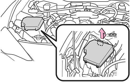
Engine Compartment Fuse Box Diagram
Push the tabs in and lift the lid off.

| № | Name | A | Circuit |
|---|---|---|---|
| 1 | MIR HTR | 7.5A | Outside rear view mirror defoggers |
| 2 | RDI | 25A | Electric cooling fan |
| 3 | PUSH-AT | 7.5A | Engine control unit |
| 4 | ABS №1 | 40A | ABS |
| 5 | HEATER | 50A | Air conditioning system |
| 6 | WASHER | 10A | Windshield washer |
| 7 | WIPER | 30A | Windshield wipers |
| 8 | RR DEF | 30A | Rear window defogger |
| 9 | RR FOG | 10A | - |
| 10 | D FR DOOR | 25A | Power window (driver’s side) |
| 11 | CDS | 25A | Electric cooling fan |
| 12 | D-OP | 25A | - |
| 13 | ABS №2 | 25A | ABS |
| 14 | D FL DOOR | 25A | Power window (passenger’s side) |
| 15-20 | SPARE | Spare fuses (One of each of the following spare fuses are provided: 7.5A, 10A, 15A, 20A, 25A, 30A.) | |
| 21 | ST | 7.5A | Starting system |
| 22 | ALT-S | 7.5A | Charging system |
| 23 | STR LOCK | 7.5A | - |
| 24 | D/L | 20A | Power door lock |
| 25 | ETCS | 15A | Engine control unit |
| 26 | AT+B | 7.5A | Transmission |
| 27 | AM2 №2 | 7.5A | - |
| 28 | EFI (CTRL) | 15A | Engine control unit |
| 29 | EFI (HTR) | 15A | Multiport fuel injection system / sequential multiport fuel injection system |
| 30 | EFI (IGN) | 15A | Starting system |
| 31 | EFI (+B) | 7.5A | Engine control unit |
| 32 | HAZ | 15A | Turn signal lights, emergency flashers |
| 33 | MPX-B | 7.5A | Gauge and meters |
| 34 | F/PMP | 20A | Multiport fuel injection system / sequential multiport fuel injection system |
| 35 | IG2 MAIN | 30A | SRS airbag system, engine control unit |
| 36 | DCC | 30A | Interior light, wireless remote control, main body ECU |
| 37 | HORN №2 | 7.5A | Horn |
| 38 | HORN №1 | 7.5A | Horn |
| 39 | H-LP LH LO | 15A | Left-hand headlight (low beam) |
| 40 | H-LP RH LO | 15A | Right-hand headlight (low beam) |
| 41 | H-LP LH HI | 10A | Left-hand headlight (high beam) |
| 42 | H-LP RH HI | 10A | Right-hand headlight (high beam) |
| 43 | INJ | 30A | Multiport fuel injection system / sequential multiport fuel injection system |
| 44 | H-LP WASHER | 30A | - |
| 45 | AM2 №1 | 40A | Starting system, engine control unit |
| 46 | EPS | 80A | Electric power steering |
| 47 | A/B MAIN | 15A | SRS airbag system |
| 48 | ECU-B | 7.5A | Wireless remote control, main body ECU |
| 49 | DOME | 20A | Interior light |
| 50 | IG2 | 7.5A | Engine control unit |
Advertisements
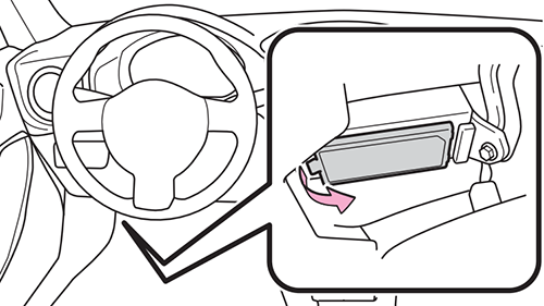
Instrument Panel Fuse Box Diagram
Remove the lid.
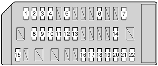
| № | Name | A | Circuit |
|---|---|---|---|
| 1 | ECU ACC | 10A | Main body ECU, outside rear view mirrors |
| 2 | P/POINT №2 | 15A | Power outlet |
| 3 | PANEL | 10A | Illumination |
| 4 | TAIL | 10A | Tail lights |
| 5 | DRL | 10A | Daytime running light system |
| 6 | STOP | 7.5A | Stop lights |
| 7 | OBD | 7.5A | On-board diagnosis system |
| 8 | HEATER-S | 7.5A | Air conditioning system |
| 9 | HEATER | 10A | Air conditioning system |
| 10 | FR FOG LH | 10A | - |
| 11 | FR FOG RH | 10A | - |
| 12 | BK/UP LP | 7.5A | Back-up lights |
| 13 | ECU IG1 | 10A | ABS, electric power steering |
| 14 | AM1 | 7.5A | Starting system |
| 15 | AMP | 15A | Audio system |
| 16 | AT UNIT | 15A | Transmission |
| 17 | GAUGE | 7.5A | Gauge and meters |
| 18 | ECU IG2 | 10A | Engine control unit |
| 19 | SEAT HTR LH | 10A | - |
| 20 | SEAT HTR RH | 10A | - |
| 21 | RADIO | 7.5A | Audio system |
| 22 | P/POINT №1 | 15A | Power outlet |
Advertisements