
Advertisements
Fuse box diagram (fuse layout), location, and assignment of fuses Rover 200 (1995, 1996, 1997, 1998, 1999).
Checking and Replacing Fuses
Fuses are simple circuit breakers, which protect the car’s electrical equipment by preventing the electrical circuits from being overloaded.
A blown fuse may be indicated when the item of electrical equipment it protects, stops working.
Only replace a fuse with one of the same or lower rating.
- Turn off the starter switch and all electrical equipment before changing a fuse.
- Remove the fuse box, then refer to the chart to identify the suspect fuse.
- Press the removal tweezers (located in the fuse box) onto the head of the fuse and pull to remove. A blown fuse can be recognized by a break in the wire.
- Replace a blown fuse with another of the same, or lower ratings. Note that there are a number of spare fuses located along the lower side of the fuse box.
If a replacement fuse fails almost immediately, refer the problem to your dealer or a qualified workshop as soon as possible.
Notice
- Never use a fuse of a higher or lower amperage rating than that specified. Never replace a broken fuse with anything other than a new fuse (such as wire, foil, etc). This could damage the electrical system or cause a fire.
Passenger Compartment Fuse Box
To access the interior fuse box, remove the cover by using a small coin to twist the three turn-buckles 90° anti-clockwise (see bottom inset), then release the cover rearwards.
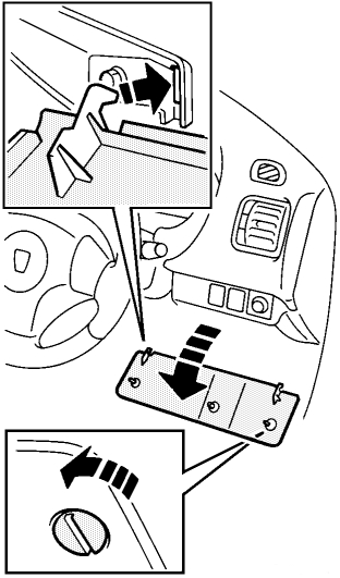
To replace the cover: locate and align the two hinges at the bottom of the cover with the slots in the surrounding panel (see top inset), close the cover and twist the turn-buckles 90° clockwise to secure.
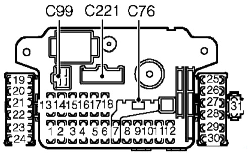
| № | A | Description |
|---|---|---|
| 1 | 10 | Indicators, dim-dip, instruments |
| 2 | 10 | Antilock brakes |
| 3 | 10 | Clock, radio, interior light |
| 4 | 15 | Headlight - right main |
| 5 | 15 | Headlight - left main |
| 6 | 30 | Sunroof |
| 7 | 5 | SRS |
| 8 | 10 | Tail light - left |
| 9 | 10 | Rear fog guard/MFU |
| 10 | 10 | Headlight - left dipped |
| 11 | 10 | Headlight - right dipped |
| 12 | 15 | Tail light - right |
| 13 | 15 | Wash/wipe - front |
| 14 | 10 | Engine management |
| 15 | 15 | Cooling fan, wash/wipe - rear |
| 16 | 10 | Reverse, stop lights |
| 17 | 10 | Radio, clock, MFU |
| 18 | 10 | Door mirrors, heater motor |
| 19 | 10 | Cooling fan |
| 20 | 10 | Engine crank |
| 21 | 20 | Window - driver |
| 22 | 20 | Window - passenger |
| 23 | 25 | HRW |
| 24 | 10 | Dim-dip |
| 25 | 10 | Illumination - daylight running |
| 26 | 20 | Power wash |
| 27 | 10 | Heated seat - passenger |
| 28 | 10 | Heated seat - driver |
| 29 | 10 | Daylight running |
| 30 | - | Not used |
| 31 | 20 | Fog lamp - front |
Advertisements
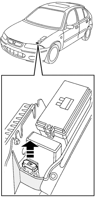
Engine Compartment Fuse Box
The fuse box is located on the left-hand side of the engine compartment. Press the catch (arrowed in the illustration) to release the cover.
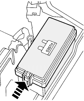
Owners are advised against removing or replacing the fuses, relays and fusible links identified on the underside of the fuse box lid as: BATTERY (80 A), ENG MGMT (40 A PETROL, 50 A DIESEL), LIGHTS (40 A), HRW/SUNROOF (40 A), IGN SWB (40 A) and IGN SWA (40 A). Failure of any of these items should be investigated by a Rover dealer.
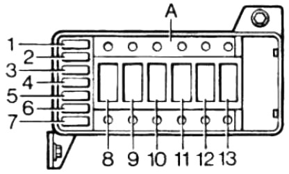
| № | A | Description |
|---|---|---|
| 1 | 15 | CDL |
| 2 | 15 | Hazards |
| 3 | 15 | MFU/horn |
| 4 | 20 | Radiator fan |
| 5 | 15 | Engine management |
| 6 | 20 | Air con |
| 7 | 20 | Heater motor |
| 8 | 40 | Ignition switch A |
| 9 | 40 | Ignition switch B |
| 10 | 40 | HRW/sunroof/window lift |
| 11 | 40 | Lights |
| 12 | 40 | Engine management |
| 13 | 80 | Main fuse |
ABS Fuse
An additional fuse (rated at 40 amps), protecting the anti-lock braking system, is attached to the battery tray where shown in the illustration.
Advertisements