
Advertisements
Fuse box diagram (fuse layout), location, and assignment of fuses and relays Renault Twingo I (2000, 2001, 2002, 2003, 2004).
Checking and Replacing Fuses
Your vehicle’s electrical system is protected from overloading by fuses. If any electrical component does not work, check the condition of the fuses. If a fuse has blown, the inside element will be melted.
Before changing a fuse, it is necessary to:
- Switch off the ignition and all electrical consumers,
- Identify the failed fuse using the fuse allocation tables and diagrams below,
- Identify and correct the cause of the problem.
When replacing a fuse, you must always:
- Use the special tweezer to extract the fuse from its holder and check the condition of its element,
- Replace a failed fuse by one of the same rating (same colour); the use of a different rating fuse could cause a fault (risk of fire).
If the same fuse blows again, avoid using that system and have the vehicle’s electrical system checked by a Renault dealer or a qualified workshop as soon as possible.
Notice
- Never use a fuse of a higher or lower amperage rating than that specified. Never replace a broken fuse with anything other than a new fuse (such as wire, foil, etc). This could damage the electrical system or cause a fire.
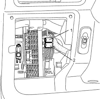
Passenger Compartment Fuse Box
The fuse panel is located behind the cover to the left of the steering wheel.
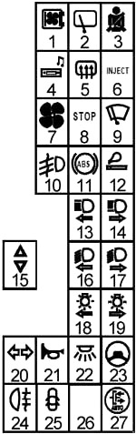
| № | A | Protected components |
|---|---|---|
| 1 | 20 | Engine connection unit |
| 2 | 15 | Rear screen wiper, Reversing lights, Windscreen/rear window washer pump |
| 3 | 10 | Pretensioners, Air bag, Engine immobiliser |
| 4 | 10 | Radio |
| 5 | 20 | Heated rear window |
| 6 | 20 | Injection |
| 7 | 20 | Heating/air conditioning fan unit |
| 8 | 15 | Brake lights |
| 9 | 15 | Windscreen wiper |
| 10 | 10 | Rear fog lights |
| 11 | 10 | Anti-lock braking system |
| 12 | 25 | Cigarette lighter, Sunroof |
| 13 | 15 | Left-hand main beam headlight |
| 14 | 15 | Right-hand main beam headlight |
| 15 | 30 | Electric window winders |
| 16 | 15 | Left-hand dipped headlight |
| 17 | 15 | Right-hand dipped headlight |
| 18 | 10 | Left side lights |
| 19 | 10 | Right-hand side lights |
| 20 | 25 | Indicators, Rear fog light, UCH |
| 21 | 10 | Horn, Engine immobiliser |
| 22 | 10 | Interior lighting/Short circuit, Diagnostic socket |
| 23 | 10 | Electrical power-assisted steering |
| 24 | - | Not in use |
| 25 | 15 | Electric door locking, Electric rear-view mirrors |
| 26 | - | - |
| 27 | 2 | Sequential gearbox |
| 1 | Not in use | |
| 2 | Front fog lights relay | |
Relay Box
This board is located under the dashboard beside the pedals.
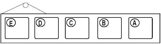
| № | Protected components |
|---|---|
| A | Sequential transmission |
| B | Not in use |
| C | Sequential gearbox starting |
| D | Not in use |
| E | Not in use |
Advertisements
Engine Compartment Fuse Box Diagram
The block is near the battery.
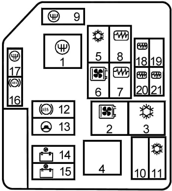
| № | A | Protected components |
|---|---|---|
| 9 | 30 | Sequential gearbox |
| 10 | - | Not in use |
| 11 | 40 | Air conditioning |
| 12 | 30 | Anti-lock braking system |
| 13 | 30 | Electrical power-assisted steering |
| 14 | 60 | Passenger compartment |
| 15 | 60 | Passenger compartment |
| 16 | 20 | Sequential gearbox |
| 17 | 30 | Anti-lock braking system |
| 18 | 10 | Injection |
| 19 | - | Not in use |
| 20 | 25 | Injection |
| 21 | 15 | Injection |
| 1 | 50 | Sequential gearbox |
| 2 | 50 | Fan assembly (with air conditioning) |
| 3 | 25 | Low speed fan (with air conditioning) |
| 4 | - | Not in use |
| 5 | 25 | Air conditioning compressor |
| 6 | 25 | Fan assembly (except air conditioning) |
| 7 | 25 | Injection locking |
| 8 | 25 | Fuel pump |
Advertisements