Advertisements
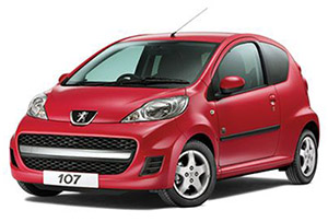
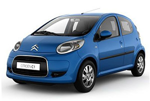
Fuse box diagram (fuse layout), location, and assignment of fuses Peugeot 107 & Citroen C1 (2005, 2006, 2007, 2008, 2009, 2010, 2011, 2012, 2013, 2014).
Checking and Replacing Fuses
Your vehicle’s electrical system is protected from overloading by fuses. If any lights, accessories, or controls in the vehicle do not work, inspect the appropriate circuit protector. If a fuse has blown, the inside element will be melted.
Before changing a fuse, it is necessary to:
- Immobilise the vehicle and switch off the ignition,
- Switch off all electrical consumers,
- Identify the failed fuse using the fuse allocation tables and diagrams in the following pages,
- Identify and correct the cause of the problem.
When replacing a fuse, you must always:
- Use the special tweezer (located in the fusebox under the bonnet) to extract the fuse from its holder and check the condition of its element,
- Replace a failed fuse by one of the same rating (same colour); the use of a different rating fuse could cause a fault (risk of fire).
If the same fuse blows again, avoid using that system and have the vehicle’s electrical system checked by PEUGEOT dealer or a qualified workshop as soon as possible.
Notice
- Never use a fuse of a higher or lower amperage rating than that specified. This could damage the electrical system or cause a fire.
- Never replace a broken fuse with anything other than a new fuse (such as wire, foil, etc). Use always an intact fuse of the same color.
- Your vehicle’s electrical system is designed to operate with standard or optional equipment. Before installing other electrical equipment or accessories on your vehicle, contact a PEUGEOT dealer or a qualified workshop.
The fuseboxes are located under the instrument panel trim and next to the battery in the engine compartment.
Passenger Compartment Fuse Boxes
These are located on each side of the instrument panel under the trim.
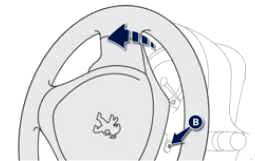
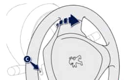
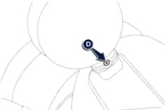
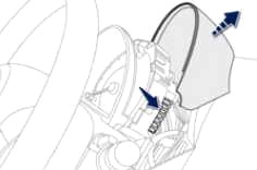
To access:
- If necessary, unlock the steering using the key.
- Turn the steering wheel to the left, remove bolt B.
- Turn the steering wheel to the right, remove bolt C.
- For the rev counter, partially unscrew bolt D located behind it.
- Raise the instrument panel trim, and the rev counter trim if necessary, to gain access to the fuses located on the left and on the right.
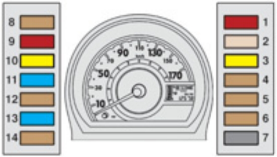
| № | A | Functions |
|---|---|---|
| 1 | 10 | Brake lamps - ABS - 2 Tronicgearbo |
| 2 | 25 | Central locking/unlocking - Remote control |
| 3 | 20 | Rear screen demisting |
| 4 | 7.5 | Rear lamps - Number plate lamps - Instrument panel - Screen - headlamp adjustment - LED daytime runninglamps -Sidelamps |
| 5 | 7.5 | Diagnostic socket |
| 6 | 7.5 | 2 Tronicgearbox - Rearfoglamp - ESP - LED daytime runninglamps - Instrument panel - Rev counter |
| 7 | 7.5 | Demisting |
| 8 | 7.5 | ABS/ESP - Power steering- Fan assembly |
| 9 | 10 | Reversinglamps - Central locking/unlocking - Electric windows - Rear screen demisting - Speedometer - Airconditioning - Heating - Rev counter - Remote control |
| 10 | 20 | Front and rear wipers and screenwash |
| 11 | 15 | Audio equipment - 12 V socket (120 W max) |
| 12 | 7.5 | Heated rear screen - ABS - Fan assembly - Front and rear wipers and screenwash - Power steering - Central locking/unlocking - Air conditioning- Heating - Electric windows - Speedometer - Rev counter - Remote control - Reversinglamp |
| 13 | 15 | Airbag - Fuel injection system - 2 Tronicgearbox - Instrument panel - Rev counter - LED daytime runninglamps |
| 14 | 7.5 | Air conditioning - Heating |
| 15 | 40 | Audio system - 12 V socket - Front and rear wipers - Power steering - ABS/ESP - Coolingfan assembly |
| 16 | 30 | Electric windows |
| 17 | 40 | Air conditioning - Heating |
Advertisements
Engine Compartment Fuse Box
To access: Unclip the cover, pressing on the right on lug (E), to gain access to the fuses. The tweezer (A) and the replacement fuses (B) are fixed at the front of the box.
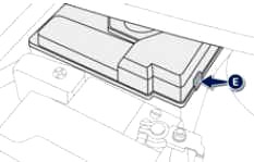
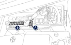
Diagram 2005-2012
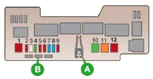
| № | A | Functions |
|---|---|---|
| 1 | 50 | 2 Tronic gearbox |
| 2 | 10 | Headlamps |
| 20 | Headlamps with daytime running lamps | |
| 3 | 30 | ABS/ESP control unit |
| 4 | 30 | Ignition switch supply |
| 5 | 10 | Hazard warning lamps - Instrument panel warning lamps - Direction indicators |
| 6 | 10 | Headlamps |
| 7 | 15 | Courtesy lamp - Speedometer - Audio equipment - Instrument panel - Rev counter |
| 8 | 15/25 | Petrol/Diesel engine control unit |
| 9 | 10 | Horn |
| 10 | 30 | Fan assembly (petrol) |
| 11 | 50 | ABS/ESP |
| 12 | 50 | Power steering |
Diagram 2012-2014
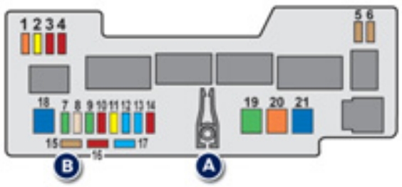
| № | A | Functions |
|---|---|---|
| 1 | 5 | LED daytime running lamps |
| 2 | 20 | Front foglamps |
| 3 | 10 | Left hand front lamp |
| 4 | 10 | Right hand front lamp |
| 5 | 7.5 | 2 Tronic gearbox - Fuel injection system |
| 6 | 7.5 | 2 Tronic gearbox - Fuel injection system |
| 7 | 30 | LED daytime running lamps - Front foglamps |
| 8 | 25 | ABS |
| 30 | ABS/ESP (with VSC) | |
| 9 | 30 | Starter motor - Heated rear screen - ABS - Coolingfan assembly - Front and rear wipersand screenwash - Power steering - Centrallocking/unlocking - Air conditioning - Heating - Electric windows - Speedometer - Rev counter - Remote control - Reversinglamp - Airbag - Fuel injection system - 2 Tronic gearbox - Instrument panel - LEDdaytime runninglamps |
| 10 | 10 | Hazard warning lamps - Instrument panel - Rev counter - Direction indicators |
| 11 | 20 | Left hand front lamp - Right hand front lamp |
| 12 | 15 | Courtesy lamp - Speedometer - Audiosystem - Instrument panel - Rev counter |
| 13 | 15 | Fuel injection system - Cooling fan assembly |
| 14 | 10 | Horn |
| 15 | 7.5 | Replacement fuse |
| 16 | 10 | Replacement fuse |
| 17 | 15 | Replacement fuse |
| 18 | 50 | 2 Tronic gearbox |
| 19 | 30/40 | Cooling fan assembly |
| 20 | 40 | ABS |
| 50 | ABS/ESP (with VSC) | |
| 21 | 50 | Power steering |
Advertisements
