Advertisements
Fuse box diagram (fuse layout), location, and assignment of fuses and relays Opel Vivaro B / Vauxhall Vivaro B (2014, 2015, 2016, 2017, 2018).
Checking and Replacing Fuses
A fuse is an element for protecting the electrical system. A fuse will trip (i.e. it will blow) in the event of a failure or improper interventions in the electrical system.
If an electrical device is not working, check whether the respective fuse is blown. Look at the silver-colored band inside the fuse. If the band is broken or melted, replace the fuse. Check those fuses first that protect the failed component, but check all the fuses before deciding that a blown fuse is not the cause. Replace any blown fuses with another with the same amperage (same color) and check the component’s operation.
Notice
- Before replacing a fuse, turn off the respective switch and the ignition.
- Never use a fuse of a higher or lower amperage rating than that specified. This could damage the electrical system or cause a fire.
- Never replace a broken fuse with anything other than a new fuse (such as wire, foil, etc). Use always an intact fuse of the same color.
Passenger Compartment Fuse Box
The fuse box is located on the left side of the instrument panel – behind the cover on the LHD vehicles, or in the glove box on the RHD. The additional relay box is on the right side – in the glove box on the LHD, or behind the cover on the LHD.
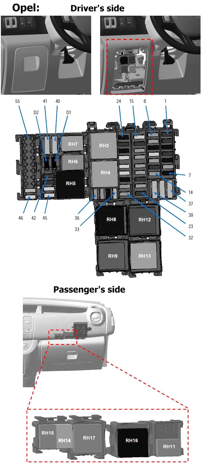
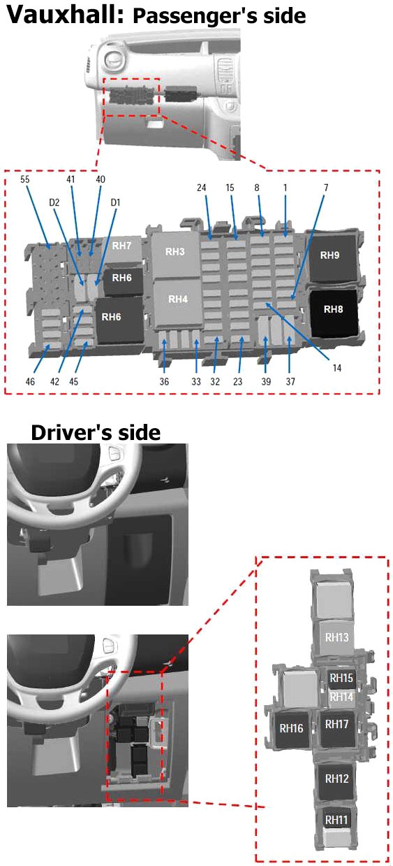
| № | A | Fused function |
|---|---|---|
| F1 | 30 | + battery feed rear window wiper |
| F2 | 10 | Main electromagnetic horn |
| F3 | 15 | + battery feed boot accessories socket |
| F4 | 30 | + battery feed driver's window lift motor time delay |
| F5 | 15 | + current distribution rear accessories socket |
| F6 | 5 | BCM start-up + |
| F7 | 15 | + after ignition feed heated seats |
| F8 | 5 | + EMM battery feed (after ignition feed charge on VSC) AVS,AUO |
| 15 | + EMM battery feed (after ignition feed charge on VSC) SOP03C | |
| F9 | 5 | + overall current distribution |
| F10 | 15 | + cigarette lighter socket or front accessory socket current distribution |
| F11 | 25 | + EMM battery feed (R daytime running lights, front position, R main beam headlights, L dipped beam headlights) |
| F12 | 5 | + timed battery feed brake lights, ABS, transponder |
| F13 | 10 | + timed battery feed interior lights and air conditioning |
| F14 | 5 | + timed battery feed steering wheel angle Stop and Start keyless vehicle |
| F15 | 25 | + After ignition feed rear window wiper, window washer pump, horn |
| F16 | 10 | Overall + after ignition feed |
| F17 | 5 | + after ignition feed reverse gear lights |
| F18 | 5 | + after ignition feed stop switch |
| F19 | 5 | + after ignition feed injection, starter relay, BCM |
| F20 | 5 | + after ignition feed airbag, column lock |
| F21 | 30 | + after ignition feed passenger window lift switch |
| F22 | 5 | + after ignition feed power steering pump |
| F23 | 10 | + EMM battery feed brake lights |
| F24 | 15 | + battery feed BCM (+ timed battery feed) |
| F25 | 10 | + battery feed BCM, electronic calculation units tyre pressure monitoring system and keyless vehicle |
| F26 | 15 | + battery feed BCM for hazard warning and direction lights |
| F27 | 25 | + battery feed BCM for locking of opening elements |
| F28 | 25 | + EMM battery feed for L daytime running lights, rear position, Lmain beam headlights, R dipped beam headlights |
| F29 | 25 | + EMM battery feed number plate position, front and rear fog lights |
| F30 | 15 | + battery feed single lever, alarm, horn |
| F31 | 5 | + battery feed dashboard |
| F32 | 5 | + battery feed single lever |
| F33 | 20 | + battery feed tow bar socket preequipment |
| F34 | 15 | (supplied in tow bar kit) |
| F35 | 5 | + battery feed circuit breaker radio, multimedia, mirrors, fault finding socket |
| F36 | 5 | + feed mirror heater |
| F37 | 10 | + timed battery feed electric mirrors, additional adapter unit UCE |
| F38 | 40 | + battery feed circuit breaker tachygraphy |
| F39 | 40 | + battery feed windscreen wiper |
| F40 | 20 | + battery feed current distribution relay 1 (heating, air conditioning) |
| F41 | 15 | + current distribution feed pre-equipment additional adaptations |
| F42 | 10 | + battery feed heater |
| F43 | 10 | + feed engine running additional adaptation |
| F44 | 25 | + feed engine running heater |
| F45 | 25 | + after ignition feed additional air conditioning unit |
| F46 | 25 | + after ignition feed relayed for keyless vehicle |
| F47 | 20 | + EMM battery feed for non-load shed current distribution relay |
| F48 | - | - |
| F49 | - | - |
| F50 | - | - |
| F51 | - | - |
| F52 | - | - |
| F53 | - | - |
| F54 | - | - |
| F55 | - | - |
| RH3 | 40 | Windscreen wiper relay |
| RH4 | 40 | Windscreen wiper 2nd speed relay |
| RH5 | 40 | + after ignition feed relay heating and rear air conditioning |
| RH6 | 20 | Support relay water pump heater matrix |
| RH7 | 20 | Driver's door electrical unlocking relay (SDO) |
| RH8 | 70 | + current distribution relay № 1 |
| RH9 | 40 | + current distribution relay № 2 |
| RH11 | 20 | Electric window lift relay |
| RH12 | 40 | Mirrors + rear window heater relay |
| RH13 | 40 | Rear window wiper relay |
| RH14 | 20 | Door central locking relay |
| RH15 | 20 | Electric window lift relay |
| RH16 | 40 | After ignition feed relay № 2 (hands-free card vehicles) |
| RH17 | 40 | Engine running + relay |
| RH18 | - | - |
| RH19 | - | - |
| RH20 | - | - |
| D1 | - | |
| D2 | - | |
Advertisements
Engine Compartment Fuse Box Diagram
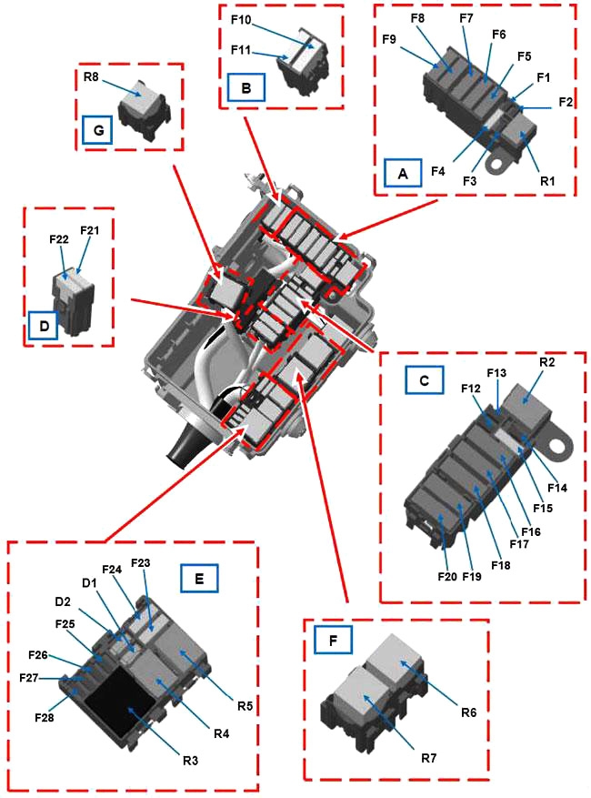
| № | A | Fused function |
|---|---|---|
| F1 | - | - |
| F2 | - | - |
| F3 | 25 | ABR/ESP |
| F4 | 30 | Starter |
| F5 | 70 | Passenger compartment 1 |
| F6 | 70 | Passenger compartment 3 |
| F7 | 50 | ABR/ESP |
| F8 | 60 | Passenger compartment 2 |
| F9 | 20 | Mirrors heater |
| 40 | Rear window + mirrors heater | |
| F10 | - | - |
| F11 | - | - |
| F12 | - | - |
| F13 | - | - |
| F14 | 15 | + battery feed air conditioning compressor |
| F15 | 15 | Fuel pump |
| F16 | 70 | Heater control unit |
| F17 | 60 | Heating element unit |
| F18 | 60 | Heating element unit |
| F19 | 40 | Engine suffix *408 and air conditioning or 450 and heating Motor-driven fan assembly 1 |
| 50 | Engine suffix *408 and heating or 450 and air conditioning Motor-driven fan assembly 1 | |
| F20 | 40 | Engine suffix *408 and air conditioning or 450 Motor-driven fan assembly 2 |
| F21 | - | - |
| F22 | - | - |
| F23 | - | - |
| F24 | - | - |
| F25 | - | - |
| F26 | 25 | Diesel heater |
| F27 | 20 | Engine injection system |
| F28 | 15 | Engine injection system |
| R1 | 20 | Starting |
| R2 | 20 | Fuel pump relay |
| R3 | 40 | Injection supply relay |
| R4 | 20 | Compressor control relay |
| R5 | - | - |
| R6 | 70 | Highspeed (Motor-drivenfan assembly 1) |
| R7 | 40 | Low speed (Motor-driven fan assembly) |
| R8 | 40 | Highspeed (Motor-drivenfan assembly 2) |
| D1 | Air conditioning compressor | |
| D2 | - | |
Electrical Distribution Unit
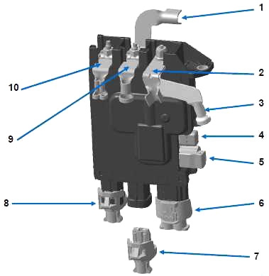
| № | A | Fused function |
|---|---|---|
| 1 | - | Battery protection supply wiring |
| 2 | 300 | Engine wiring (Alternator) |
| 3 | 300 | Engine wiring (starter motor) |
| 4 | 5 | Mini fuse with cap (Start/Stop) |
| 5 | 5 | Cab wiring (Start/Stop) |
| 6 | 50 | Cab wiring (conversion KPD and KC6 options or trailer tow bar) |
| 7 | - | Reserved for purpose-body builder conversions |
| 8 | 35 | Engine wiring (engine management) |
| 9 | - | Engine Connection Unit |
| 10 | 120 | Cab wiring (power steering) |
Advertisements
