
Advertisements
Fuse box diagram (fuse layout), location, and assignment of fuses and relays Opel Vivaro A / Vauxhall Vivaro A (2001, 2002, 2003, 2004, 2005, 2006, 2007, 2008, 2009, 2010, 2011, 2012, 2013, 2014).
Checking and Replacing Fuses
A fuse is an element for protecting the electrical system. A fuse will trip (i.e. it will blow) in the event of a failure or improper interventions in the electrical system.
If an electrical device is not working, check whether the respective fuse is blown. Look at the silver-colored band inside the fuse. If the band is broken or melted, replace the fuse. Check those fuses first that protect the failed component, but check all the fuses before deciding that a blown fuse is not the cause. Replace any blown fuses with another with the same amperage (same color) and check the component’s operation.
Notice
- Before replacing a fuse, turn off the respective switch and the ignition.
- Never use a fuse of a higher or lower amperage rating than that specified. This could damage the electrical system or cause a fire.
- Never replace a broken fuse with anything other than a new fuse (such as wire, foil, etc). Use always an intact fuse of the same color.
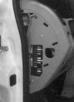
Instrument Panel Fuse Box Diagram
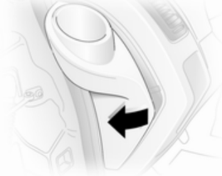
Located on the left-hand side of the instrument panel, below the cupholder. Remove the ashtray from the lefthand cup holder and pull open the fuse box cover. Do not store any objects behind the cover.

| № | Fused function |
|---|---|
| 1 | Not used |
| 2 | Radio |
| 3 | Not used |
| 4 | Not used |
| 5 | Not used |
| 6 | Not used |
| 7 | AC, rear |
| 8 | Not used |
| 9 | Fog lamps |
| 10 | Central locking |
| 11 | Interior illumination |
| 12 | Diagnostic plug, immobiliser |
| 13 | Rear screen heating |
| 14 | Rear screen wiper/washer system |
| 15 | Screen wipers |
| 16 | Brake light |
| 17 | ABS |
| 18 | Not used |
| 19 | Window winders |
| 20 | Window winders |
| 21 | Seat heating |
| 22 | Not used |
| 23 | Not used |
| 24 | Radio |
| 25 | Heating |
| 26 | Accessories |
| 27 | High beam, left |
| 28 | High beam, right |
| 29 | Low beam, left |
| 30 | Low beam, right |
| 31 | Tail lamp, left |
| 32 | Tail lamp, right |
| 33 | Rear fog lamp |
| 34 | Horn |
| 35 | Mirror heating |
| 36 | Windscreen heating control |
| 37 | Not used |
| 38 | Not used |
| 39 | Not used |
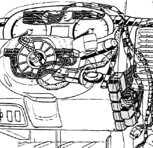
The relay for the electronic thermostat is installed on the left-hand side of the air mixer and distributor.
Advertisements
Relay Box
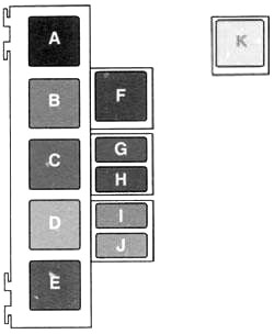
| № | Relay |
|---|---|
| A | Relay for the rear screen heating |
| B | Time-out for rear screen wipers |
| C | Relay for the rear screen wipers |
| D | Relay + after-contact |
| E | AC tripping relay |
| F | Relay for the heatable windscreen |
| G | Relay for the fog lamps |
| H | "Headlight” relay for low beam |
| I | "Headlight” relay for parking lights |
| J | "Headlight” main relay |
| K | Relay for the electronic thermostat |
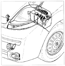
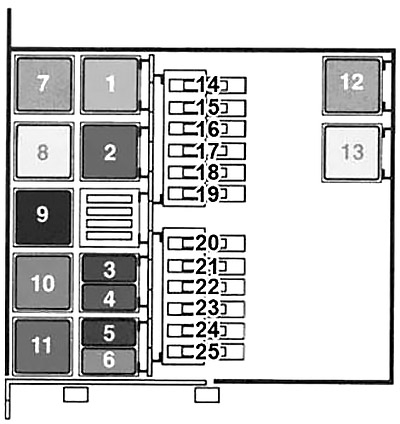
Engine Compartment Fuse Box
Advertisements
| № | A | Fused function |
|---|---|---|
| 14 | - | Not used |
| 15 | - | Not used |
| 16 | 40 | AC |
| 17 | 50 | Windscreen heating |
| 18 | 50 | Windscreen heating |
| 19 | 60 | PDB |
| 20 | 60 | ABS |
| 21 | 60 | PDB |
| 22 | 60 | PDB |
| 23 | 50 60 70 | Radiator fan |
| 24 | 50 60 | Warning autofuse |
| 25 | 70 | Pre-heating |
| 1 | Auxiliary heater: 2 or 3 add-on heater | |
| Diesel: Parking heater relay | ||
| 2 | Diesel: Relay for fuel injection computer | |
| Petrol: Injection interrupt | ||
| 3 | Diesel pump relay | |
| 4 | Fuel pump/diesel pre-heating relay | |
| 5 | Diesel parking heater: Relay for fan unit, second speed level | |
| 6 | Coupling relay: AC compressor | |
| 7 | 1 add-on heater (thermo-plunger) relay | |
| 8 | 2 or 3 add-on heater (thermo-plungers) | |
| Petrol: Parking heater relay | ||
| 9 | Diesel: Fan unit | |
| Diesel: Relay for second speed level with AC | ||
| Petrol: First speed level with AC | ||
| 10 | Petrol: Fan unit | |
| Diesel: Relay for first speed level of the fan with AC | ||
| Petrol: Second speed level with AC | ||
| 11 | Not used | |
| 12 | Relay for heatable windscreen. | |
| 13 | Relay for heatable windscreen. | |
In the diesel version, the vehicle is either equipped with an auxiliary heater or with a parking heater.
Advertisements