
Advertisements
Fuse box diagram (fuse layout), location, and assignment of fuses and relays Nissan X-Trail (T32) (2014, 2015, 2016, 2017, 2018).

Checking and Replacing Fuses
Fuses and fusible links protect your vehicle’s electrical system from short-circuiting or overloading. If electrical parts in your vehicle are not working, the system may have been overloaded causing a blown fuse. Before you replace or repair any electrical parts, check the appropriate fuses.
- Be sure the ignition switch is pushed to the OFF or LOCK position and all switch are OFF.
- Open the fuse box cover.
- On the fuse diagram, find the number of the fuse you want to check. The diagram tells you where to locate the fuse on the panel. Pinch the fuse perpendicularly with the fuse puller and pull it out.
- To check a fuse, look at the silver-colored band inside the fuse. If the band is broken or melted, replace the fuse with a new one.
- If a new fuse also opens, have the electrical system checked and repaired by a Nissan dealer or a repair facility of your choice.
Notice
- Never use a fuse of a higher or lower amperage rating than that specified. This could damage the electrical system or cause a fire.
- Never replace a broken fuse with anything other than a new fuse (such as wire, foil, etc). Use always an intact fuse of the same color.
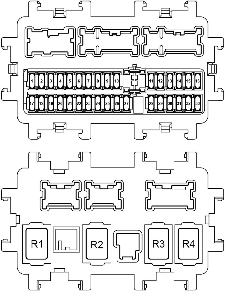
Instrument Panel Fuse Box
Left-hand drive
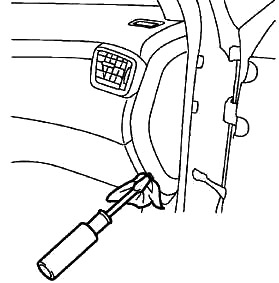
The fuses are located on the driver’s side of the dash panel. Remove the fuse box cover.
Right-hand drive
The fuse panel is behind the glove box.
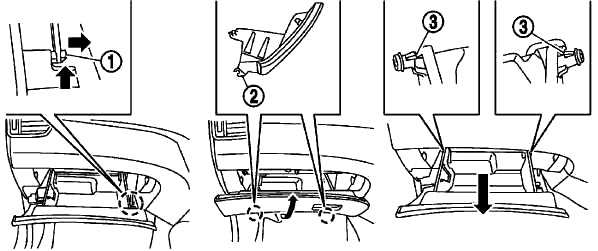
To access:
- Open the glove box and unlock the damper (1).
- Hold the glove box lid so that the distance between the upper end of the lid and the dashboard is about 5 cm (2 in), and then pull off the hinges (2) located on the underside of the lid.
- Unlock the left and right stoppers (3) and remove the glove box lid.
| № | A | Circuit Protected |
|---|---|---|
| 1 | 15 | Turn Lamp, Hazard Lamp (Body Control Module (BCM)) |
| 2 | 5 | 4WD Control Unit |
| 3 | 20 | Central Locking (Body Control Module (BCM)) |
| 4 | 15 | Rear wiper (Body Control Module (BCM)) |
| 5 | 20 | Central Locking (Body Control Module (BCM)) |
| 6 | 10 | 4WD Control Unit, Data Link Connector, Electric Parking Brake Control Unit |
| 7 | 10 | Body Control Module (BCM) |
| 8 | 5 | Clutch Interlock Switch |
| 9 | 5 | NATS Antenna Amplifier |
| 10 | 10 | Stop Lamp Switch, Body Control Module (BCM) |
| 11 | 20 | Audio Unit |
| 12 | 10 | Subwoofer (Option Connector 8) |
| 13 | 10 | Combination Meter |
| 14 | 5 | Body Control Module (BCM), Sensor Cancel Switch, Siren Control Unit |
| 15 | 20 | Audio Unit, Navi Control Unit , Around View Monitor Control Unit |
| 16 | 20 | Audio Unit, Navi Control Unit , Around View Monitor Control Unit |
| 17 | 15 | Blower Motor, A/C Amp., Power Transistor (auto A/C) |
| 18 | 10 | Spare |
| 19 | 20 | Cigar lighter |
| 20 | 10 | A/C Amp., A/C Auto Amp., Brake Pedal Position Switch, A/C Control, Door Mirror Remote Control Switch, Stop Lamp Switch (R9M) |
| 21 | 10 | ABS Actuator and Control Unit |
| 22 | 10 | Door Mirror (Driver Side), Door Mirror (Passenger Side) |
| 23 | 15 | Condenser (Rear Windows Defogger) |
| 24 | 15 | Condenser (Rear Windows Defogger) |
| 25 | 20 | Interior Room Lamp Relay (Body Control Module (BCM)), Option Connector 8 |
| 26 | 5 | Audio Unit, Navi Control Unit, Headlight Range Control |
| 27 | 15 | Blower, A/C, Engine Restart Bypass Relay |
| 28 | 15 | Front Heated Seat Switch LH, Front Heated Seat Switch RH |
| 29 | 10 | DC/DC Converter (Ignition Relay - Fuse №: 54, 55, 56, 57) |
| 30 | 10 | Sonar Control Unit, Steering Angle Sensor, Stop Lamp Switch, 4WD Control Unit, EPS Control Unit, Data Link Connector, Audio Unit, Navi Control Unit, Around View Monitor Control Unit, Electric Parking Brake Control Module, Chassis Control Module, Auto Anti-dazzling Inside Mirror, Option Connector (8), Combination Switch (spiral Cable), Fuel Heater Relay, Distance Sensor, Front Camera Unit, PTC Relay-1, PTC Relay-2, PTC Relay-3, Ignition Relay (with Stop / Start System) |
| 31 | 5 | Combination Meter, Diode 1 (with Stop / Start System) |
| 32 | 10 | Air Bag Diagnosis Sensor Unit |
| 33 | 15 | Combination Switch, Pump Control Unit |
| R1 | Ignition | |
| R2 | Blower | |
| R3 | Rear Windows Defogger | |
| R4 | Accessory | |
Advertisements
Additional Fuse Panel (with Stop / Start System)
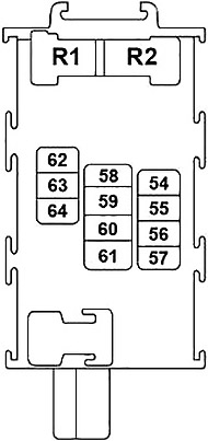
| № | A | Circuit Protected |
|---|---|---|
| 54 | 10 | Steering Angle Sensor |
| 55 | 10 | Diode 2 |
| 56 | 10 | Around View Monitor Control Unit, Distance Sensor, Front Camera Unit, Audio Unit |
| 57 | 10 | Engine Control Module, Transmission Control Module, Transmission Range Switch, IPDM E/R (intelligent Power Distribution Module Engine Room), Neutral Position Switch, Primary Speed Sensor, Secondary Speed Sensor, Input Speed Sensor, Transmission Range Switch, Back-up Lamp Switch |
| 58 | - | Not Used |
| 59 | 10 | A/C |
| 60 | 10 | ABS Actuator and Control Unit |
| 61 | - | Not Used |
| 62 | - | Not Used |
| 63 | 20 | Audio Unit, Navi Control Unit , Around View Monitor Control Unit |
| 64 | - | Not Used |
| R1 | Accessory | |
| R2 | Ignition | |
J/B №2
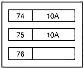
| № | A | Circuit Protected |
|---|---|---|
| 74 | 10 | Electric Oil Pump Relay |
| 75 | 10 | Transmission Control Module |
| 76 | - | Not Used |
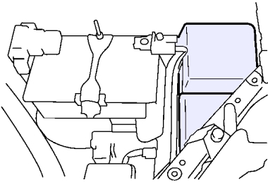
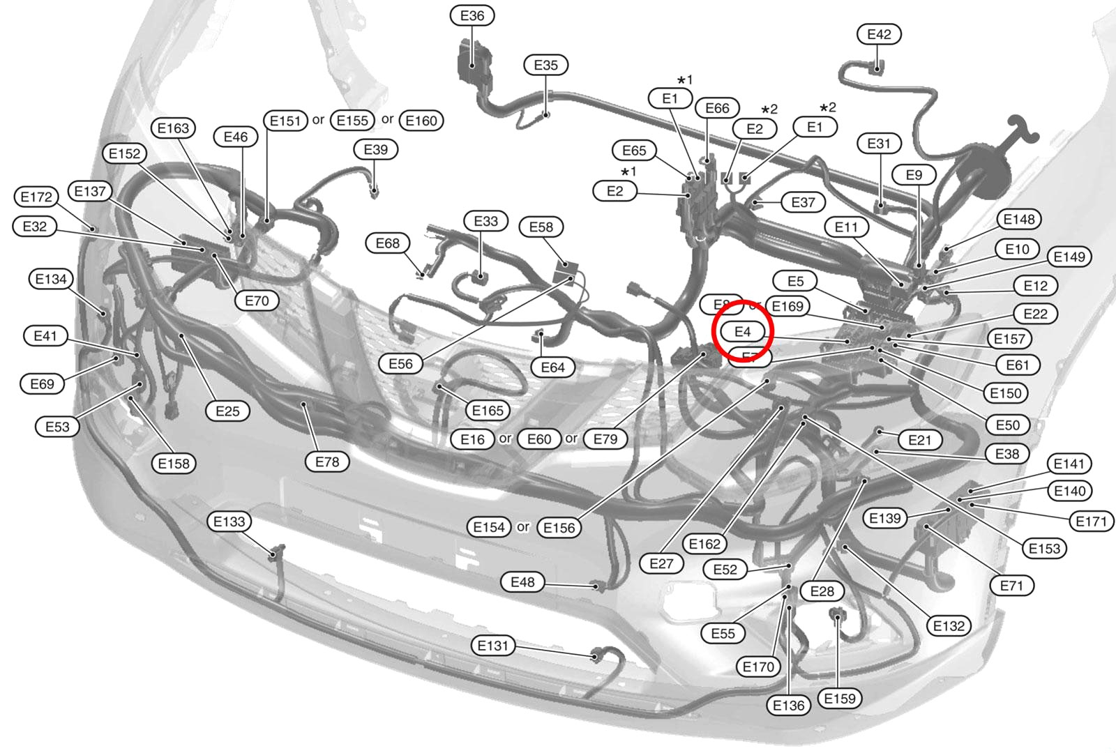
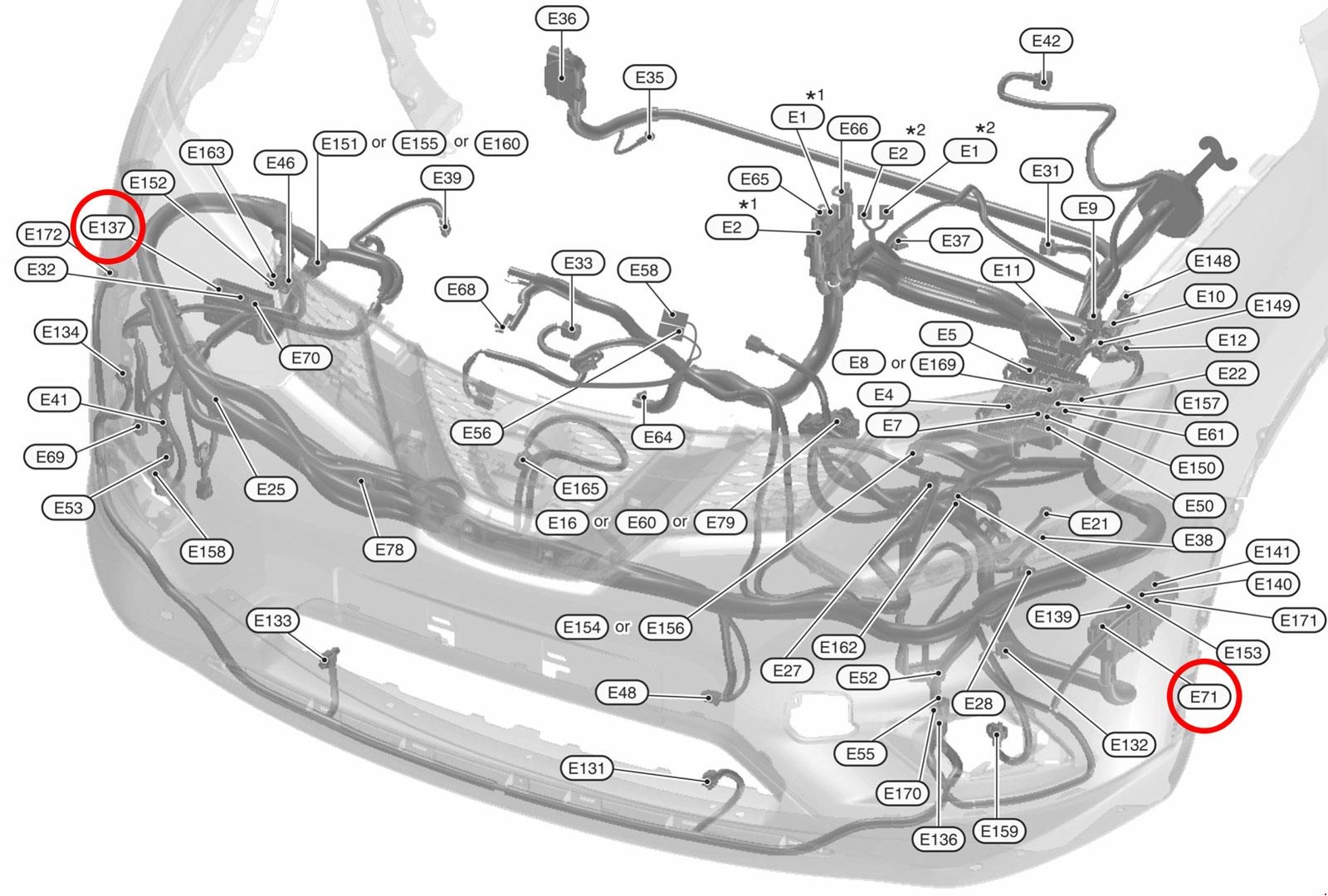
Engine Compartment Fuses
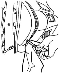
Remove the fuse/fusible link box cover by using a suitable tool and pushing the tab.
To remove the air duct and resonator:
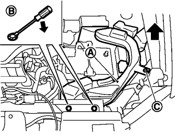
- Remove the clips with a suitable tool.
- Loosen the bolt with a suitable tool.
- Pull the air duct and resonator upward and then sideways if necessary.
To install the air duct and resonator, perform the procedure in reverse order.
Advertisements
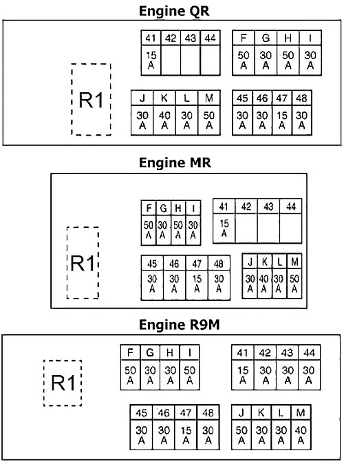
Fuse Box №1 Diagram (E4)
| № | A | Circuit Protected |
|---|---|---|
| 41 | 15 | Horn Relay 1 |
| 42 | 30 | R9M: PTC Relay 2 |
| 43 | 30 | R9M: PTC Relay 3 |
| 44 | 30 | R9M: PTC Relay 1 |
| 45 | 30 | Electric Parking Brake Control Unit |
| 46 | 30 | Option Connector 9 |
| 47 | 15 | Horn Relay 2 |
| 48 | 30 | Electric Parking Brake Control Unit |
| F | 50 | ESP Control Unit |
| 50 | R9M: Power Window Relay, Power Window Main Switch, Sunroof Motor Assembly, Sunshade Motor Assembly, Power Window Relay, Lumbar Support Switch, Lumbar Support Switch, Power Window Main Switch, Power Seat Switch (Driver Side), Power Seat Switch (Passenger Side) | |
| G | 30 | ABS Actuator and Control Unit |
| H | 50 | ESP Control Unit |
| 30 | R9M: Cooling Fan Relay 2 | |
| I | 30 | Headlamp Washer Relay |
| 50 | R9M: ESP Control Unit | |
| J | 30 | Automatic Back Door Control Unit |
| 50 | R9M: ESP Control Unit | |
| K | 40 | ABS Actuator and Control Unit |
| 30 | R9M: Cooling Fan Relay 2 | |
| L | 30 | Starter Control Relay, Fuse Block (J/B), Ignition Relay |
| M | 50 | Power Window Relay, Power Window Main Switch, Sunroof Motor Assembly, Sunshade Motor Assembly, Power Window Relay, Lumbar Support Switch, Lumbar Support Switch, Power Window Main Switch, Power Seat Switch (Driver Side), Power Seat Switch (Passenger Side) |
| 40 | R9M: ABS Actuator and Control Unit | |
| R1 | Horn Relay | |
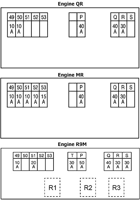
Fuse Box №2 Diagram (F116)
| № | A | Circuit Protected |
|---|---|---|
| 49 | 10 | Transmission Control Module |
| 50 | 10 | Cooling Fan Relay 4, Cooling Fan Relay 5 |
| 51 | 10 | High Pressure Fuel Pump Relay |
| 20 | R9M: Fuel Heater Relay | |
| 52 | 10 | Main Relay |
| 53 | 15 | Main Relay |
| T | 30 | Automatic Back Door Control Unit |
| P | 40 | Cooling Fan Relay 1 |
| 50 | R9M: Glow Control Unit | |
| Q | 40 | IPDM E/R |
| R | 30 | Engine Control Module (Throttle Control Motor Relay) |
| S | 30 | Headlamp Washer Relay |
| R1 | Starter Control | |
| R2 | Engine Restart Bypass Relay | |
| R3 | Fuel Heater Relay | |
Advertisements
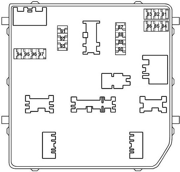
Fuse Box №3 Diagram (IPDM E/R)
| № | A | Circuit Protected |
|---|---|---|
| 81 | 10 | Engine Control Module |
| 82 | 15 | Engine Control Module |
| 83 | 15 | Throttle Control Motor Relay, Engine Control Module, EVAP Canister Purge Volume Control Solenoid Valve, Mass Air Flow Sensor, Condenser, Ignition Coil №1 (with Power Transistor), Ignition Coil №2 (with Power Transistor), Ignition Coil №3 (with Power Transistor), Ignition Coil №4 (with Power Transistor), Fuel Injector Relay, Exhaust Valve Timing Control Solenoid Valve, Intake Valve Timing Control Solenoid Valve, High Pressure Fuel Pump Relay, Fuel Injector №1, Fuel Injector №2, IPDM E/R (intelligent Power Distribution Module Engine Room), Fuel Injector №3, Fuel Injector №4, Fuel Flow Actuator, Air Fuel Ratio (A/F) Sensor, Engine Coolant Bypass Valve Control Solenoid Valve, Fuel Heater And Water In Fuel Level Sensor |
| 84 | 10 | Engine Control Module, Exhaust Valve Timing Control Solenoid Valve, Intake Valve Timing Intermediate Lock Control Solenoid Valve, Intake Valve Timing Control Solenoid Valve, Intake Manifold Runner Control Valve |
| 85 | 15 | Air Fuel Ratio (A/F) Sensor 1, Heated Oxygen Sensor 2, Turbocharger Boost Control Solenoid Valve, Engine Control Module, Glow Control Unit |
| 86 | 15 | Fuel Injector №1, Fuel Injector №2, Fuel Injector №3, Fuel Injector №4, Condenser, Ignition Coil №1 (with Power Transistor), Ignition Coil №2 (with Power Transistor), Ignition Coil №3 (with Power Transistor), Ignition Coil №4 (with Power Transistor), IPDM E/R (Intelligent Power Distribution Module Engine Room), Fuse № Q (Cooling Fan Relay 1 (Cooling Fan Motor 2, Cooling Fan Relay 2, Resistor (R9M)) |
| 87 | 15 | A/C Relay (Compressor) |
| 88 | - | Not Used |
| 89 | - | Not Used |
| 90 | 30 | Front Wiper Relay (Front Wiper Motor) |
| 91 | 20 | Fuel Pump Relay (Engine Control Module, Fuel Pump Control Unit, Fuel Level Sensor Unit, Fuel Pump) |
| 92 | - | Not Used |
| 93 | 10 | Engine Control Module, Transmission Control Module, Transmission Range Switch, IPDM E/R (Intelligent Power Distribution Module Engine Room), Neutral Position Switch, Primary Speed Sensor, Secondary Speed Sensor, Input Speed Sensor, Reverse / Neutral Position Switch, Fuse №57 (with Stop / Start System) |
| 94 | - | Not Used |
| 95 | 5 | Steering Lock Unit |
| 96 | 10 | Engine Restart Relay |
| 97 | 10 | Compressor, Front Combination Lamp RH, Front Combination Lamp LH, Transmission Range Switch, Neutral Position Switch, Back-up Lamp Switch, Reverse / Neutral Position Switch |
Fusible Link Block
It is on the battery “+” terminal.
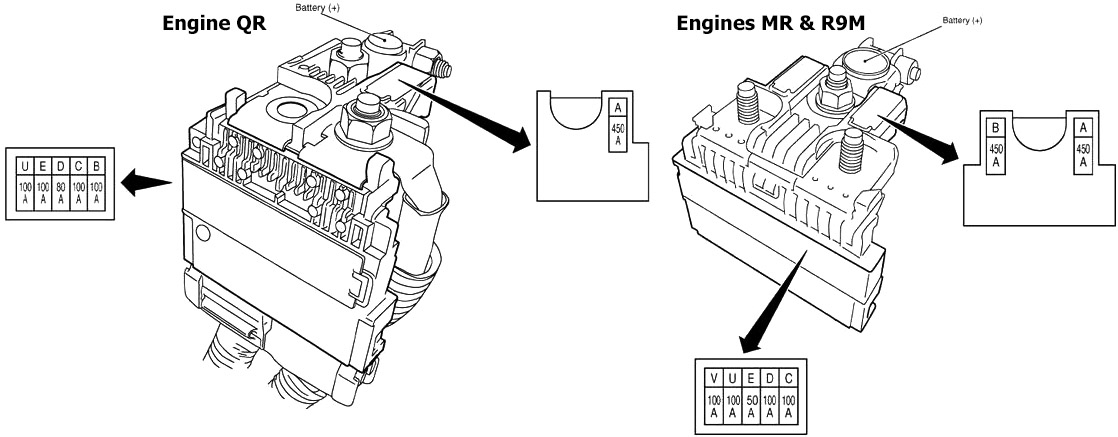
| № | A | Circuit Protected |
|---|---|---|
| A | 450 | Alternator, Starter Motor (QR, MR), Engine Restart Bypass Relay, Fuse № F (ESP) |
| B | 100 | Alternator, Starter Motor, Engine Restart Bypass Relay, Fuse № F (ESP) |
| 450 | Alternator, Starter Motor, Engine Restart Bypass Relay, Fuse № F (ESP) | |
| C | 100 | MR, R9M: Fuse Block (J/B) - (Accessory Relay, BCM, Fuse №: 7, 25), Blower Relay (Fuse №: 17, 27) |
| D | 80 | IPDM E/R |
| 100 | IPDM E/R, Thermoplunger Control Unit (R9M) | |
| E | 100 | QR: Fuse Block (J/B) - (Accessory Relay, BCM, Fuse №: 7, 25), Blower Relay (Fuse №: 17, 27) |
| 50 | Fuse Block (F116) | |
| U | 100 | Fuse Block (F116), Ignition Relay |
| V | 100 | ESP |
Additional Fuses
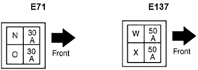
| № | A | Circuit Protected |
|---|---|---|
| N | 30 | DC/DC Converter, Fuse Block (J/B) № 63 - (Audio Unit, Navi Control Unit , Around View Monitor Control Unit) |
| With Stop / Start System: DC/DC Converter - Fuse Block (J/B) - (Accessory Relay, Fuse №: 20, 59, 60) | ||
| O | 30 | DC/DC Converter, Fuse Block (J/B №2) №: 74 (Electric Oil Pump Relay), 75 (Transmission Control Module) |
| W | 50 | Thermoplunger Control Unit (R9M) |
| X | 50 | Thermoplunger Control Unit (R9M) |
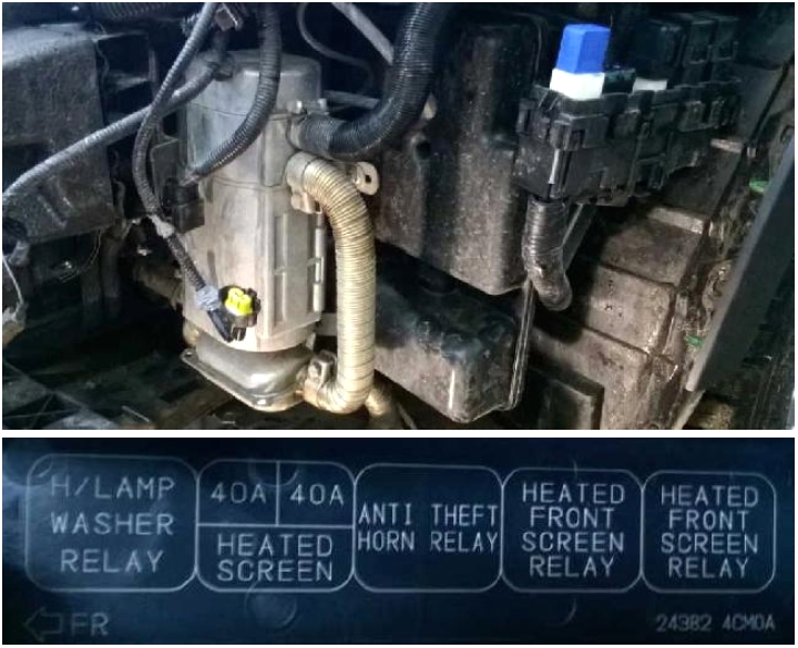
Relay Box
Advertisements