
Advertisements
Fuse box diagram (fuse layout), location, and assignment of fuses and relays Mitsubishi Pajero / Montero / Shogun (1999, 2000, 2001, 2002, 2003, 2004, 2005, 2006).

Checking and Replacing Fuses
To prevent damage to the electric system due to short-circuiting or overloading, each individual circuit is provided with a fuse.
Use the fuse location diagrams and the matching tables, to check the fuse that is related to the problem. Look through the clear side of the fuse to see if the metal wire inside is separated. If it is, the fuse is blown and should be replaced. Use a fuse puller (located in the passenger compartment fuse block lid) to remove the fuses. Clamp it on the fuse you wish to remove, and pull the fuse straight out from the fuse block. Insert a new fuse of the same capacity securely into the appropriate slot.
If any system does not function but the fuse corresponding to that system is normal, there may be a fault in the system or elsewhere. Have your vehicle checked by an authorized MITSUBISHI dealer.
Notice
- Before replacing a fuse, always turn off the electrical circuit concerned and place the ignition switch in the “LOCK” position.
- Do not repair fuses and never use a fuse with a capacity greater than the one listed or any substitute, such as wire, foil, etc. This would cause the circuit wiring to heat up and could cause a fire.
- If the replacement fuse blows again after a short time, have the electrical system checked by an authorized Mitsubishi Motors dealer or a repair facility of your choice to find and correct the cause.
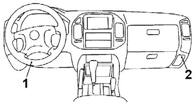
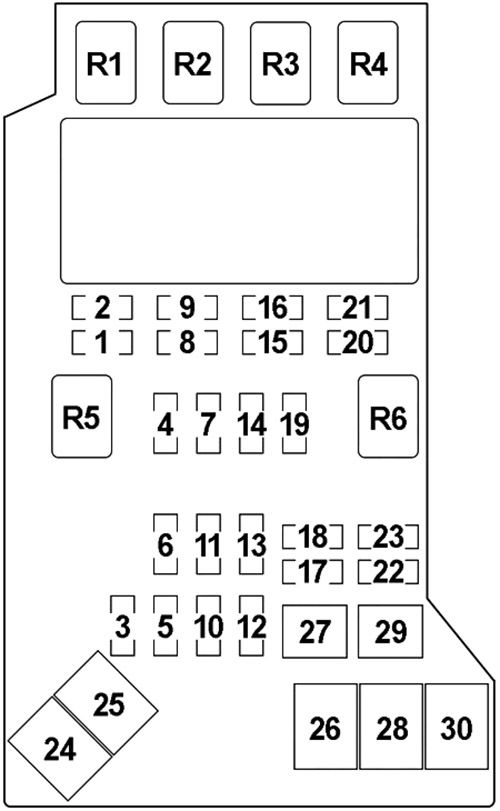
Instrument Panel Fuse Box
The fuse block is located behind the lid in the instrument panel. Pull the fuse box lid to remove it.
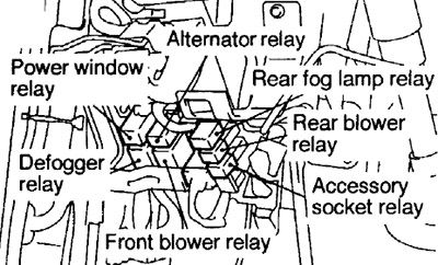
1) Fuse Box / Rear Fog Lamp / Rear Blower / Accessory Socket
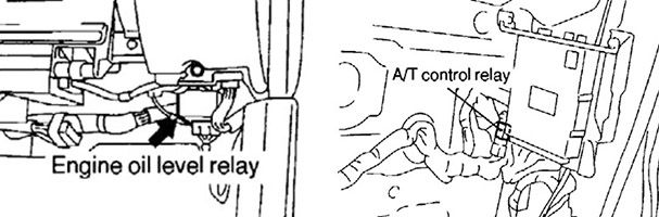
2) Engine Oil Level / A/T Control Relay
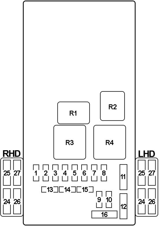
Fuse Box Diagram
Advertisements
| № | A | Protected Component |
|---|---|---|
| 1 | 15 | A/C-ECU, ETACS-ECU, Rear Washer Motor, Rear Wiper Motor, Remote Controlled Mirror |
| 2 | - | - |
| 3 | - | - |
| 4 | 15 | Cigarette Lighter, Center Display |
| 5 | 15 | ABS-ECU, ABS G Sensor, A/C Compressor Relay, A/C-ECU, A/C Switch, Automatic Compressor-ECU, Condenser Fan Relay, Defog-ger Relay, Front Blower Relay, Front-ECU, Front Rear Fan Switch, Fuel Line Heater Relay, HBB Buzzer, Motor Relay 2, Outside/inside Air Selection Damper Control Motor, PTC Heater Relay, Rear A/C Control Unit, Rear A/C Switch, Rear A/C Unit, Rear Blower Relay, Rear Cooler Control Unit, Rear Cooler Switch, Rear Cooler Unit, Rear Heater Control Unit, Rear Heater Switch, Rear Heater Unit, Sunroof Motor Assembly, Transfer-ECU, Valve Relay, Wiper Deicer Switch, Wiper Deicer Relay |
| 6 | 10 | Auto-Cruise Control Switch, Combination Meter, Column-ECU, EGR Solenoid Valve №1, EGR Solenoid Valve №2, ETACS-ECU, GDI ECO Indicator Lamp-ECU, Immobilizer-ECU (4D5), Rear Differential Lock-ECU, Solenoid Valve A, Solenoid Valve B, SRS-ECU, Throttle Valve Controller, Vehicle Speed Sensor, 4WD Indicator-ECU |
| 7 | 20 | Combination Meter, Fuel Pump Module, Fuel Pump Relay |
| 8 | 10 | Combination Meter, Engine-A/T-ECU, Engine-ECU, ETACS-ECU, Front Propeller Shaft Speed Sensor, Input Shaft Speed Sensor, Output Shaft Speed Sensor, SRS-ECU, Transfer-ECU, Rear Propeller Shaft Speed Sensor, SC G Sensor |
| 9 | 10 | Rear Fog Lamp Relay, Rear Combination Lamp |
| 10 | 20 | ETACS-ECU, Diagnosis Connector |
| 11 | 30 | Automatic Compressor-ECU, Defogger, Fuse (Passenger Compartment): "25" |
| 12 | 30 | A/C Switch, Automatic Compressor-ECU, Blower Resistor, Blower Motor, Blower Linear Controller |
| 13 | - | - |
| 14 | - | - |
| 15 | - | - |
| 16 | - | - |
| 24 | 10 | HBB, EBD, ABS |
| 25 | 10 | Defogger, Door Mirror Heater |
| 26 | 20 | Sunroof |
| 27 | 20 | Heated Seat |
| R1 | Power Window | |
| R2 | Alternator | |
| R3 | Front Blower | |
| R4 | Defogger | |
Engine Compartment Fuse Box
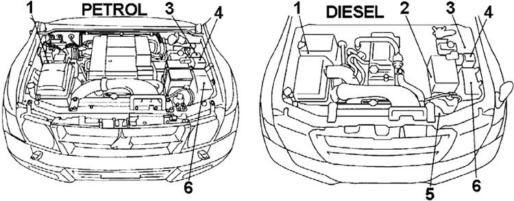
- RHD: Relay Box №2
- Diesel: Glow Plug Relay
- LHD: Relay Box №2
- Relay Box №1
- 4M4: PTC Heater Relay
- Fuse Box
Advertisements
Fuse Box Diagram
| № | A | Protected Component |
|---|---|---|
| 1 | 10 | Horn |
| 2 | 20 | Windshield Wiper, Washer |
| 3 | 20 | Fuel Pump |
| 4 | 10 | Accessory Socket, Clock, Motor Antenna, Radio, Center Display Circuit |
| 5 | 25 | PTC Heater |
| 6 | 25 | Condenser Fan |
| 7 | 10 | Clock, Combination Meter, Door Lamp, Ignition Key Cylinder Illumination Lamp, Center Display, Radio, Tape Player, Room Lamp, Sunroof, ECU Power Supply |
| 8 | 10 | Combination Meter, Engine-A/T-ECU, Engine-ECU, Tail Lamp |
| 9 | 10 | Tail Lamp |
| 10 | 15 | Accessory socket |
| 11 | 20 | Rear Blower |
| 12 | 25 | Fuel Line Heater |
| 13 | 15 | Wiper Deicer |
| 14 | 10 | A/C Compressor |
| 15 | 10 | Headlamp (Low Beam) |
| 16 | 10 | Headlamp (Low Beam), Headlamp Leveling |
| 17 | - | - |
| 18 | 20 | Engine-A/T-ECU, A/T-ECU Power |
| 19 | 20 | Front Fog Lamp |
| 20 | 10 | Headlamp (High Beam) |
| 21 | 10 | Headlamp (High Beam), High Beam Indicator Lamp |
| 22 | 10 | Charging, Turn-Signal Lamp |
| 23 | 15 | Stop Lamp |
| 24 | 60 | Fuse (Engine Compartment): № "5", "6", "7", "10", "11", "13", "14", "31", "32", "33" "25", Fuse (Passenger Compartment): № "9", "10", "11", "12" |
| 25 | 120 | Headlamp, Front Fog Lamp, Tail Lamp, Fuse (Engine Compartment): № "18", "22", "23", "26", "27", "29" |
| 26 | 40 | Ignition Switch |
| 27 | 30 | Power Window, Power Seat System, Fuse (Passenger Compartment): № "26" |
| 28 | - | - |
| 29 | 20 | Engine Control, INVECS-II, Immobilizer, Auto-Cruise Control System, Mitsubishi Stability Control |
| 30 | 40 | PTC Heater, Heater Idle-Up System (Diesel) |
| R1 | Condenser Fan (High Speed) | |
| R2 | Condenser Fan (Low Speed) | |
| R3 | Wiper Deicer | |
| R4 | A/C Compressor | |
| R5 | Horn | |
| R6 | Front Fog Lamp | |
Advertisements
Fuse Box №2
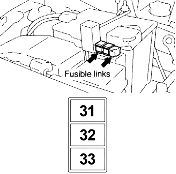
| № | A | Protected Component |
|---|---|---|
| 1 | 60 | HBB, EBD, ABS |
| 2 | 40 | HBB, EBD, ABS |
| 3 | 80 | Engine Control, Glow System (Diesel) |
Relay Box №1
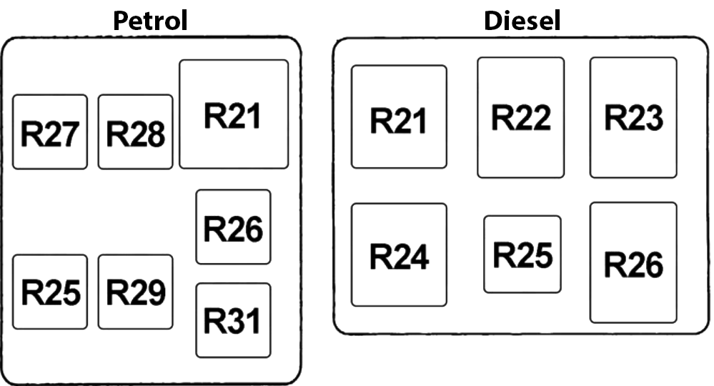
| № | Relay |
|---|---|
| R21 | ABS Valve |
| R22 | Fuel Line Heater |
| R23 | Fuel Cut |
| R24 | Starter |
| R25 | Engine Control |
| R26 | Petrol: Fuel Pump №2 |
| R27 | Fuel Pump №1 |
| R28 | Injector Driver Control |
| R29 | Throttle Control Servo |
| R31 | - |
Relay Box №2
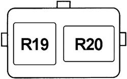
| № | Relay |
|---|---|
| R19 | ABS Motor №1 |
| R20 | ABS Motor №2 |
Advertisements