
Advertisements
Fuse box diagram (fuse layout), location, and assignment of fuses and relays Mitsubishi Lancer X (2007, 2008, 2009, 2010, 2011, 2012, 2013, 2014, 2015, 2016, 2017).

Checking and Replacing Fuses
To prevent damage to the electrical system from short-circuiting or overloading, each individual circuit is equipped with a fuse.
Use the fuse location diagrams and the matching tables, to check the fuse that is related to the problem. Look through the clear side of the fuse to see if the metal wire inside is separated. If it is, the fuse is blown and should be replaced. Use a fuse puller (located in the engine compartment fuse block) to remove the fuses. Clamp it on the fuse you wish to remove, and pull the fuse straight out from the fuse block. Insert a new fuse of the same capacity securely into the appropriate slot.
If the fuse is not blown, something else must be causing the problem. Have the system inspected by your authorized Mitsubishi Motors dealer or a repair facility of your choice
Notice
- Before replacing a fuse, always turn off the electrical item concerned to the fuse and turn the ignition switch to the “LOCK” position or put the operation mode in OFF.
- Do not repair fuses and never use a fuse with a capacity greater than the one listed or any substitute, such as wire, foil, etc. This would cause the circuit wiring to heat up and could cause a fire.
- If the replacement fuse blows again after a short time, have the electrical system checked by an authorized Mitsubishi Motors dealer or a repair facility of your choice to find and correct the cause.
This fuse list shows the names of the electrical systems and their fuse capacities. There are spare fuses in the cover of the fuse block in the engine compartment.
Instrument Panel Fuse Box
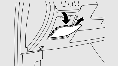
The fuse blocks in the passenger compartment are located behind the fuse lid on the driver’s side as shown. Open the fuse lid and pull to remove it.
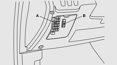
- A – Main fuse block
- B – Sub fuse block
For vehicles with the bottom cover, use the puller to loosen the 2 clips (A) and push down the bottom cover. The puller is in the fuse block in the engine compartment.
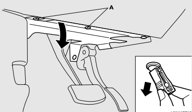
When changing fuses, do not damage the driver’s knee airbag harness or accidentally strike the airbag area with hard objects. Improper work methods could result in an accidental driver’s knee airbag deployment or could make the driver’s knee airbag inoperable. Either of these situations could result in serious injury or death.
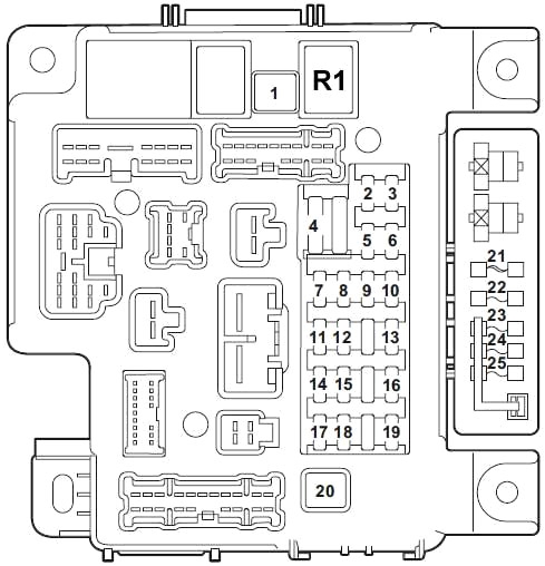
| № | A | Load circuit |
|---|---|---|
| 1 | 30 | Blower motor |
| 2 | 15 | Stop lights (Brake lights), ETACS-ECU, high-mounted stoplight, rear combination light and shift switch assembly |
| 3 | 10 | Rear fog light |
| 4 | 30 | ETACS-ECU, washer motor and windshield wiper motor |
| 5 | 10 | Data link connector |
| 6 | 20 | ETACS-ECU, front door lock actuator, trunk lid actuator and switch and rear door lock actuator |
| 7 | 15 | Audio visual navigation unit, CAN box unit, center panel unit, hands free module, radio and CD player or CD changer, rear display unit and satellite radio tuner |
| 8 | 7.5 | A/C-ECU, column switch, combination meter, ETACS-ECU, key reminder switch, KOS-ECU, power window relay, wireless control module |
| 9 | 15 | Audio visual navigation unit, center panel unit, combination meter and key reminder switch |
| 10 | 15 | ETACS-ECU, Hazard warning flasher |
| 11 | 15 | Rear window wiper |
| 12 | 7.5 | A/C control panel, A/C-ECU, CVT control relay, ABS-ECU, center panel unit, column switch, combination meter, heated seat relay, KOS-ECU, rear window defogger relay, shift switch assembly, SRS-ECU, sunroof motor assembly, wireless control module |
| 13 | 15 | Accessory socket (front floor console) and cigarette lighter |
| 14 | 10 | Ignition switch circuit |
| 15 | 20 | Sunroof motor assembly |
| 16 | 10 | Audio visual navigation unit, CAN box unit, door mirror assembly, radio and CD player or CD changer, rear display unit and remote controlled mirror switch |
| 17 | 10 | Occupant classification-ECU |
| 18 | 7.5 | Audio visual navigation unit, backup light switch |
| 19 | 15 | Accessory socket (rear floor console) |
| 20 | 30 | Front power window motor (RH), power window main switch and rear power window motor |
| 21 | 30 | Rear window defogger |
| 22 | 7.5 | Door mirror assembly |
| 23 | 15 | 115V Power outlet |
| 24 | 20 25 | Power seats |
| 25 | 30 | Heated seat |
| R1 | Blower motor | |
Advertisements
Engine Compartment Fuse Box
In the engine compartment, the fuse block is located as shown in the illustration.
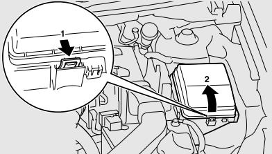
- Push the lock lever.
- Remove the fuse block cover.
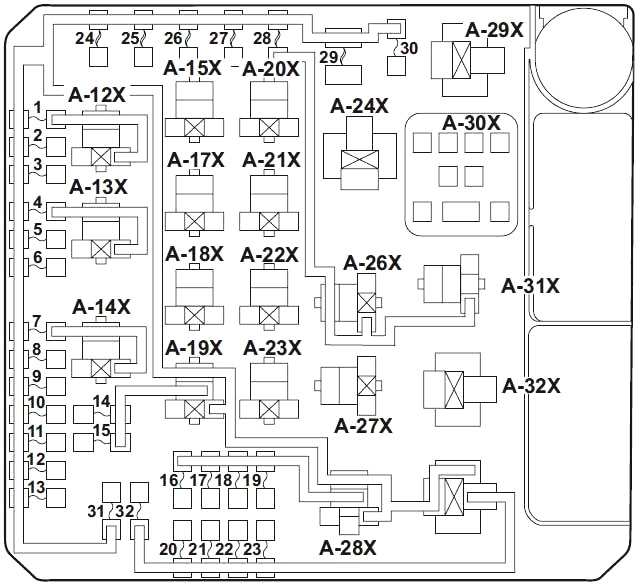
| № | A | Load circuit |
|---|---|---|
| 1 | 15 | Fog light and fog light relay |
| 2 | 7.5 | Engine control module |
| 3 | 20 | Primary pulley speed sensor |
| 4 | 10 | Horn and horn relay |
| 5 | 7.5 | Generator |
| 6 | 20 | Headlight washer |
| 7 | 10 | A/C compressor assembly and A/C compressor clutch relay |
| 8 | 15 | ETV/Oil cooler fan (Twin Clutch SST) (except for vehicles with turbocharger) |
| ETV (vehicles with turbocharger) | ||
| 9 | 20 | Security horn |
| 10 | 15 | Wiper deicer |
| 11 | - | - |
| 12 | 30 | Power gate |
| 13 | 10 | Daytime running light and daytime running light relay |
| 14 | 10 | Headlight assembly (High: LH) |
| 15 | 10 | Headlight assembly (High: RH) |
| 16 | 20 | Headlight (low/high beam) (left) |
| 17 | 20 | Headlight (low/high beam) (right) |
| 18 | 10 | Headlight assembly (Low: LH) |
| 19 | 10 | Headlight assembly (Low: RH) |
| 20 | 10 | ENG/POWER (except for vehicles with turbocharger) |
| I/C SPRAY (vehicles with turbocharger) | ||
| 21 | 10 | Ignition coil №1 to 4 |
| 22 | 20 | Center exhaust pipe heated oxygen sensor, engine control module, engine oil control valve, evaporative emission purge solenoid, evaporative emission ventilation solenoid, injector №1 to 4, mass airflow sensor, heated oxygen sensor and vehicle speed sensor |
| 25 | Fuel line heater | |
| 23 | 15 | Fuel pump module (except for vehicles with turbocharger) |
| 20 | Fuel pump module (vehicles with turbocharger) | |
| 24 | 30 | Starter |
| 25 | 40 | Valve lift control (except for vehicles with turbocharger) |
| 26 | 40 | ABS-ECU |
| 27 | 30 | ABS-ECU |
| 28 | 30 | Condenser fan motor, condenser fan relay and fan control relay |
| 29 | 40 | Radiator fan motor and radiator fan relay |
| 30 | 30 | IOD, Fuse №7 to 9 in passenger compartment |
| 31 | 30 | Audio amplifier |
| 32 | 30 | Diesel |
| A-11X | Fog light relay | |
| A-12X | Horn relay | |
| A-13X | A/C compressor clutch relay | |
| A-14X | - | |
| A-15X | CVT control relay | |
| A-16X | - | |
| A-17X | Headlight relay (High) | |
| A-18X | Throttle actuator control motor relay | |
| A-19X | - | |
| A-20X | Daytime running light relay | |
| A-21X | Injector relay | |
| A-22X | - | |
| A-23X | Condenser fan relay | |
| A-24X | Stater relay | |
| A-25X | Headlight relay (Low) | |
| A-26X | Radiator fan relay | |
| A-27X | - | |
| A-28X | Fan control relay | |
| A-29X | - | |
| A-30X | MFI relay | |
There are no 7.5 A, 25 A or 30 A spare fuses. If a fuse of one of these capacities blows, replace it temporarily by borrowing one of the fuses indicated below.
- 5 A: 10 A spare fuse
- 25 A: 20 A spare fuse
- 30 A: 30 A audio amplifier fuse
Replace the borrowed fuse with a fuse that has the correct capacity as soon as possible.
Fuse box above battery
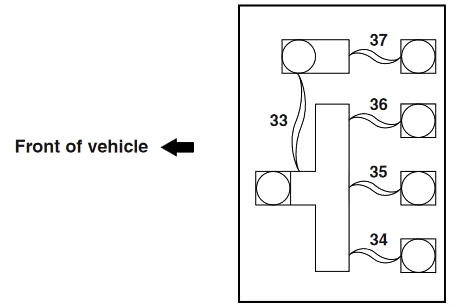
| № | A | Load circuit |
|---|---|---|
| 33 | 120 | Fusible link №37/ Fusible link №34 to 36 |
| 34 | 80 | Fuse Nos.2, 4, 5, 10, 11,12, 14, 15, 17, 18, 20 and №25 in passenger compartment |
| 35 | 80 | - |
| 36 | 120 | Fuse №1 to 32 in engine compartment, headlight relay (High), headlight relay (Low) and MFI relay |
| 37 | 80 | Fusible link №1 and 21, Fuse № 3, 6, 13, 16, 19, and 22 in passenger compartment and ETACS-ECU(ACC relay 2 and blower relay) |
Advertisements