
Advertisements
Fuse box diagram (fuse layout), location, and assignment of fuses and relays Mitsubishi Lancer, Mirage & Colt (1995, 1996, 1997, 1998, 1999, 2000, 2001, 2002, 2003).
Checking and Replacing Fuses
To prevent damage to the electrical system from short-circuiting or overloading, each individual circuit is equipped with a fuse. The fuse blocks are located in the passenger compartment and in the engine compartment.
Use the fuse location diagrams and the matching tables, to check the fuse that is related to the problem. Look through the clear side of the fuse to see if the metal wire inside is separated. If it is, the fuse is blown and should be replaced. If the fuse is not blown, something else must be causing the problem. Contact an authorized Mitsubishi Motors dealer or a repair facility of your choice to have the problem checked.
Notice
- Before replacing a fuse, always turn off the electrical circuit concerned and place the ignition switch in the “LOCK” position.
- Do not repair fuses and never use a fuse with a capacity greater than the one listed or any substitute, such as wire, foil, etc. This would cause the circuit wiring to heat up and could cause a fire.
- If the replacement fuse blows again after a short time, have the electrical system checked by an authorized Mitsubishi Motors dealer or a repair facility of your choice to find and correct the cause.
Instrument Panel Fuse Box
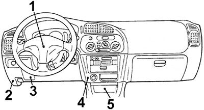
1) Windshield Intermittent Wiper Relay (Built in Colimn Switch);
2) Fuse Box;
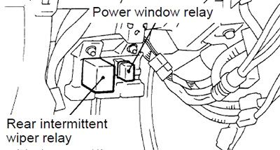
3) Power Window Relay / Rear Intermittent Wiper Relay;
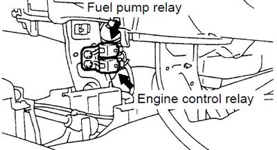
4) Fuel Pump Relay / Engine Control Relay;
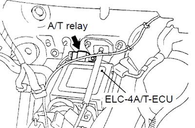
5) Automatic Transmission Control Relay.
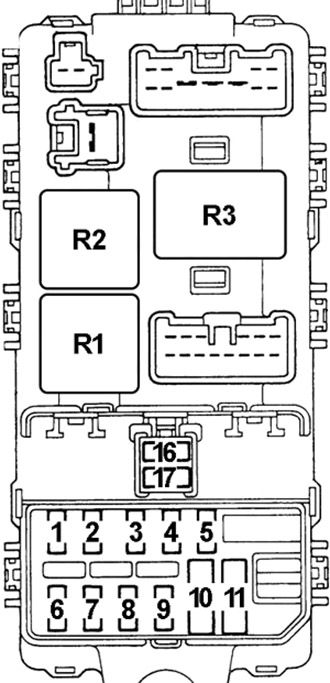
Fuse Box Diagram
| № | A | Protected Component |
|---|---|---|
| 1 | 20 | Intermittent Wiper Relay, Washer Motor and Wiper Motor |
| 2 | 10 | A/T Indicator Lamp, Back-Up Lamp, ELC-4A/T-ECU, Input Shaft Speed Sensor, Output Shaft Speed Sensor, SRS-ECU, Stop Lamp |
| 3 | 20 | ETACS-ECU (Power Door Lock) |
| 4 | 10 | Combination Meter, ETACS-ECU, SRS-ECU, Sunroof-ECU, Vehicle Speed Sensor |
| 5 | 10 | Active Yaw Control System, ABS, Back-Up Lamp, Power Door Lock, Clock & Multi-Display, Defogger & Door Mirror Heater, Full-Auto Air Conditioner, Ignition Key Cylinder Illumination Lamp, Ignition Key Reminder Buzzer, Meter & Gauge, MPI System, Radio, Room Lamp, Luggage Compartment Lamp, Cargo Room Lamp, Supplemental Restraint System, Tail Lamp, Position Lamp, Licence Plate Lamp and Lighting Monitor Buzzer |
| 6 | 10 | ABS-ECU, ABS Valve Relay, A/C Switch, Thermostat, Blower Relay, Defogger Relay, Power Window Relay, Active Yaw Control System, Tension Reducer Seat Belt |
| 7 | 15 | Cigarette Lighter, Remote Controlled Mirror |
| 8 | 10 | Power Door Lock, Clock, Multi Display, Radio |
| 9 | 10 | Turn-Signal and Hazard Warning Flasher Unit |
| 10 | 25 | Blower Motor |
| 11 | 25 | Defogger and Defogger Switch |
| 16 | 20 | Sunroof |
| 17 | - | - |
| R1 | Defogger | |
| R2 | Blower | |
| R3 | Turn-Signal and Hazard Warning Flasher Unit | |
Advertisements
Engine Compartment Fuse Boxes
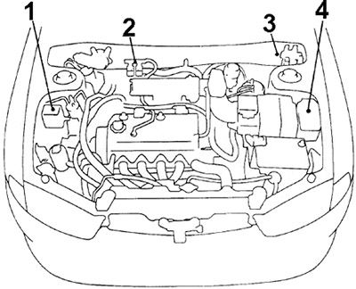
1) Relay Box;
2) ABS Valve Relay / ABS Motor Relay;
3) ABS Valve Relay / ABS Motor Relay;
4) Fuse Box.
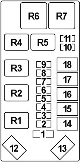
Fuse Box Diagram
| № | A | Protected Component |
|---|---|---|
| 1 | 25 | A/C Compressor, Condenser Fan Motor |
| 2 | 10 | ECU Power Supply, Luggage Compartment Lamp, Radio, Room Lamp, Meter and Gauge, MUT-II Power Supply |
| 3 | 10 | Clock, Radio |
| 4 | 10 | Horn |
| 5 | 10 | High Beam Indicator |
| 6 | 10 | EVO: Full-Auto Air Conditioner, Heater and Manual Air Conditioner |
| 7 | 10 | Tail Lamp, Illumination Lamp |
| 8 | 10 | Position Lamp and Tail Lamp |
| 9 | 15 | Fog Lamp |
| 10 | 10 | Hazard Warning Lamp |
| 11 | 15 | Stop Lamp, ABS, Active Yaw Control System |
| 12 | 60 | Fuse (Passenger Compartment): "3", "5", "10", "11", "16" |
| 13 | 100 | Alternator, Fuse (Engine Compartment): № "1", "2", "6", "12" |
| 14 | 30 | Ignition Switch |
| 15 | 40 | Alternator, Fog Lamp, Headlamp, Tail Lamp, Fuse (Engine Compartment): № "7", "8", "9" |
| 16 | 30 | Radiator Fan Motor |
| 17 | 30 | Power Windows, Power Seat |
| 18 | 20 | MPI System, ELC 4-Speed Automatic Transmission |
| R1 | - | |
| R2 | Horn | |
| R3 | - | |
| R4 | Radiator Fan Motor | |
| EVO: Radiator Fan Motor (Low) | ||
| R5 | Headlamp | |
| R6 | - | |
| R7 | Alternator | |
Advertisements
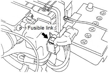
Fusible Link
Located on the Battery Positive Terminal.
| № | A | Protected Component |
|---|---|---|
| 1 | 60 | Anti-Skid Braking System (ABS) |
| 2 | 60 | Active Yaw Control System |
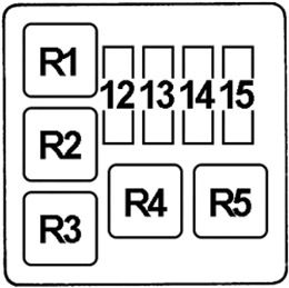
Relay Box
| № | A | Protected Component |
|---|---|---|
| 12 | 10 | A/C Compressor |
| 13 | - | - |
| 14 | 20 | EVO: Radiator Fan Motor |
| 15 | - | - |
| R1 | EVO: Radiator Fan Motor (High) | |
| R2 | - | |
| R3 | Condenser Fan | |
| R4 | Carburettor: Condenser Fan Control | |
| R5 | A/C Compressor | |
Advertisements