
Advertisements
Fuse box diagram (fuse layout), location, and assignment of fuses and relays Mitsubishi Lancer IX (2000, 2001, 2002, 2003, 2004, 2005, 2006, 2007).
Checking and Replacing Fuses
To prevent damage to the electrical system from short-circuiting or overloading, each individual circuit is equipped with a fuse.
Use the fuse location diagrams and the matching tables, to check the fuse that is related to the problem. Look through the clear side of the fuse to see if the metal wire inside is separated. If it is, the fuse is blown and should be replaced. Use a fuse puller (placed on the interior fuse box cover) to remove the fuses. Clamp it on the fuse you wish to remove, and pull the fuse straight out from the fuse block. Insert a new fuse of the same capacity securely into the appropriate slot.
If the fuse is not blown, something else must be causing the problem. Have the system inspected by your authorized Mitsubishi Motors dealer or a repair facility of your choice
Notice
- Before replacing a fuse, always turn off the electrical item concerned to the fuse and turn the ignition switch to the “LOCK” position or put the operation mode in OFF.
- Do not repair fuses and never use a fuse with a capacity greater than the one listed or any substitute, such as wire, foil, etc. This would cause the circuit wiring to heat up and could cause a fire.
- If the replacement fuse blows again after a short time, have the electrical system checked by an authorized Mitsubishi Motors dealer or a repair facility of your choice to find and correct the cause.
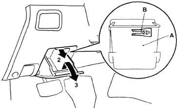
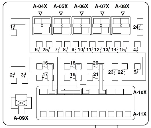
Instrument Panel Fuse Box
The fuse blocks in the passenger compartment are located behind the storage compartment to the left of the steering wheel. Open the storage compartment and pull it towards you while lifting it up to remove it.
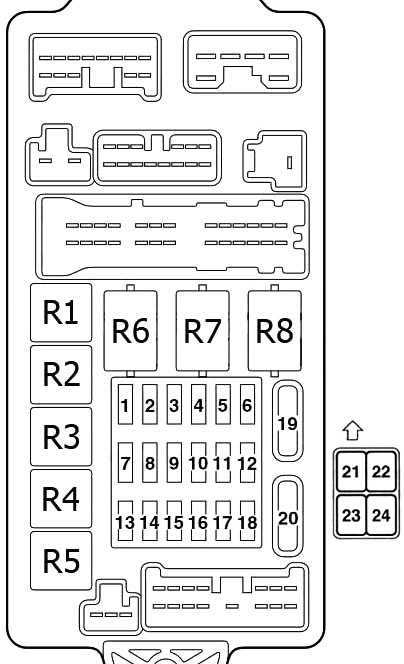
| № | A | Load circuit |
|---|---|---|
| 1 | 10 | Capacitor and ignition coil |
| 2 | 7.5 | ABS warning lamp, brake warning lamp, charging warning lamp, check engine warning lamp, column switch, combination meter, ETACS-ECU, low fuel warning lamp, oil pressure warning lamp, SRS air bag warning lamp, SRS-ECU and vehicle speed sensor |
| 3 | 7.5 | A/T control relay, combination meter, engine-A/T-ECU, ETACS-ECU, input shaft speed sensor, output shaft speed sensor, rear combination lamp and SRS-ECU |
| 4 | - | - |
| 5 | 7.5 | A/C compressor relay, A/C-ECU, blower relay, rear window defogger relay, front-ECU, heated seat relay, heater control unit and outside/inside air selection damper control motor |
| 6 | 7.5 | Remote controlled mirror |
| 7 | 20 | Front-ECU and windshield wiper motor |
| 8 | 7.5 | Engine-A/T-ECU, engine-ECU, fuel pump relay (1) and fuel pump relay (2) |
| 9 | 15 | Cigarette lighter |
| 10 | - | - |
| 11 | 7.5 | Accessory socket relay and Remote controlled mirror |
| 12 | 7.5 | ABS-ECU |
| 13 | - | - |
| 14 | 15 | ETACS-ECU and rear wiper motor |
| 15 | 15 | Diagnosis connector |
| 16 | 10 | Rear fog lamp, rear fog lamp indicator lamp and rear fog lamp relay |
| 17 | - | - |
| 18 | - | - |
| 19 | 30 | A/C-ECU, blower motor, heater control unit and resistor |
| 20 | 30 | Rear window defogger |
| 21 | 20 | Electric sunroof |
| 22 | 10 | Seat heater |
| 23 | 10 | Evaporative intercooler |
| 24 | - | - |
| 1 | Fuel pump relay (1) | |
| 2 | Heated seat relay | |
| 3 | Fuel pump relay (2) | |
| 4 | Accessory socket relay | |
| 5 | Rear fog lamp relay | |
| 6 | Power window relay | |
| 7 | Blower relay | |
| 8 | Rear window defogger relay | |
Advertisements
Engine Compartment Fuse Box
In the engine compartment, the fuse block is located as shown in the illustration.
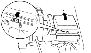
- Push the tab.
- Remove the fuse block cover.
| № | A | Load circuit |
|---|---|---|
| 1 | 60 | Fuse №15, 16, 19, 20 (in junction block) circuit |
| 2 | 50 | Fan controller |
| 3 | 60 | ABS-ECU |
| 4 | 40 | Ignition switch circuit |
| 5 | 30 | Power window main switch and power window sub switch |
| 6 | 15 | Front fog lamp, front fog lamp indicator lamp, front fog lamp relay and spare connector (for front fog lamp) |
| 7 | 10 | Horn relay and horn |
| 8 | 20 | Air cleaner air flow sensor, camshaft position sensor, emission solenoid valve (EGR system), emission solenoid valve (purge control system), engine-A/T-ECU, engine-ECU, engine control oxygen sensor, engine control relay, engine crank angle sensor, fan control relay, fuel injector, ignition coil relay, immobilizer-ECU and throttle body idle speed control servo |
| 9 | 10 | A/C compressor |
| 10 | 15 | ABS-ECU, engine-A/T-ECU, high mount stop lamp and rear combination lamp |
| 11 | 15 | Accessory socket |
| 12 | 7.5 | Alternator |
| 13 | 10 | ETACS-ECU, front turn signal lamp, rear combination lamp, side turn signal lamp and turn signal indicator lamp |
| 14 | 20 | A/T control solenoid valve assembly and engine-A/T-ECU |
| 15 | 15 | Fuel pump |
| 16 | 10 | Headlamp (RH) |
| 17 | 10 | Headlamp (LH) and high beam indicator lamp |
| 18 | 10 | Headlamp (RH) |
| 19 | 10 | Headlamp (LH), headlamp assembly and headlamp levelling switch |
| 20 | 7.5 | A/C-ECU, ashtray illumination lamp, cigarette lighter illumination lamp, combination meter, fog lamp switch, front turn signal lamp, hazard warning switch, headlamp assembly (RH), headlamp levelling switch, heated seat switch, heater control unit, licence plate lamp, rear combination lamp, rheostat, side turn signal lamp and spare connector (for audio) |
| 21 | 7.5 | Combination meter, headlamp assembly (LH), licence plate lamp, position lamp (LH) and rear combination lamp (LH) |
| 22 | 10 | Combination meter, column switch, ETACS-ECU and front-ECU |
| 23 | 10 | Clock, ETACS-ECU and spare connector (for audio) |
| 24 | - | - |
| 25 | 20 | Heated seat assembly and heated seat switch |
| 26 | 100 (4G1) 120 (4G6) | Battery, fusible link №1,2, 3, 4, 5, fuse №6, 7, 8, 9, 10, 11, 12, 13, 14, 15, 22 (relay box) and front-ECU |
| A-04X | Front fog lamp relay | |
| A-05X | Horn relay | |
| A-06X | - | |
| A-07X | - | |
| A-08X | - | |
| A-09X | Fan control relay | |
| A-10X | Front-ECU | |
| A-11X | Front-ECU | |
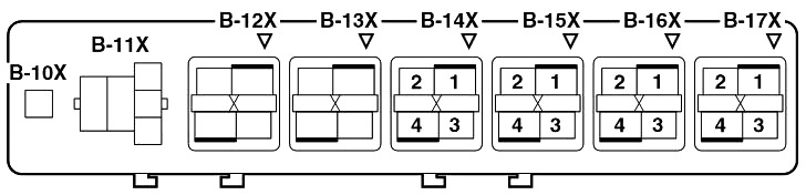
Relay Box
| № | Relays |
|---|---|
| B-10X | Engine speed detection connector |
| B-11X | - |
| B-12X | - |
| B-13X | - |
| B-14X | Ignition coil relay |
| B-15X | A/T control relay |
| B-16X | Engine control relay |
| B-17X | A/C compressor relay |
Advertisements