
Advertisements
Fuse box diagram (fuse layout), location, and assignment of fuses and relays Mitsubishi Galant (1998, 1999, 2000, 2001, 2002, 2003).

Checking and Replacing Fuses
To prevent damage to the electric system due to short-circuiting or overloading, each individual circuit is provided with a fuse.
Use the fuse location diagrams and the matching tables, to check the fuse that is related to the problem. Look through the clear side of the fuse to see if the metal wire inside is separated. If it is, the fuse is blown and should be replaced. Use a fuse puller (located in the passenger compartment fuse block lid) to remove the fuses. Clamp it on the fuse you wish to remove, and pull the fuse straight out from the fuse block. Insert a new fuse of the same capacity securely into the appropriate slot.
If any system does not function but the fuse corresponding to that system is normal, there may be a fault in the system or elsewhere. Have your vehicle checked by an authorized MITSUBISHI dealer.
Notice
- Before replacing a fuse, always turn off the electrical circuit concerned and place the ignition switch in the “LOCK” position.
- Do not repair fuses and never use a fuse with a capacity greater than the one listed or any substitute, such as wire, foil, etc. This would cause the circuit wiring to heat up and could cause a fire.
- If the replacement fuse blows again after a short time, have the electrical system checked by an authorized Mitsubishi Motors dealer or a repair facility of your choice to find and correct the cause.
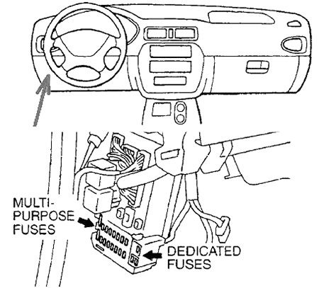
Instrument Panel Fuse Box Diagram
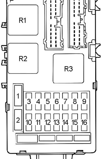
| № | A | Protected Component |
|---|---|---|
| 1 | 30 | Defogger, Remote Controlled Mirror |
| 2 | 30 | Blower Motor |
| 3 | 15 | Powertrain Control Module, ABS-ECU, Stoplight, Autocruise Control-ECU, Immobilizer-ECU |
| 4 | - | - |
| 5 | 10 | Powertrain Control Module, Input Shaft Speed Sensor, Output Shaft Speed Sensor, Backup Light, SRS-ECU |
| 6 | - | - |
| 7 | 15 | Accessory Socket, Cigarette Lighter, Remote Controlled Mirror |
| 8 | 20 | ETACS-ECU, Front-ECU |
| 9 | 10 | Sunroof-ECU, ABS Warning Light Relay, ABS-ECU |
| 10 | 10 | Horn, Horn Relay, Theft-Alarm Horn, Theft-Alarm Horn Relay |
| 11 | 15 | Data Link Connector, ETACS-ECU |
| 12 | 10 | Vehicle Speed Sensor |
| 13 | 10 | Combination Meter, ETACS-ECU, SRS-ECU, Auto-Cruise Control-ECU, Column-ECU |
| 14 | - | - |
| 15 | - | - |
| 16 | 10 | Blower Relay, Outside/Inside Air Selection Damper Control Motor, Defogger Relay, A/C Switch, Front-ECU, A/C Compressor Relay, Automatic Compressor Controller |
| R1 | Blower Motor | |
| R2 | Defogger | |
| R3 | - | |
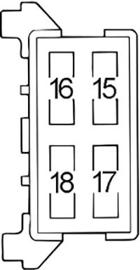
| № | A | Protected Component |
|---|---|---|
| 15 | 20 | Radio and Tape Player (7-Speakers) |
| 16 | - | - |
| 17 | 20 | Sunroof |
| 18 | 10 | Door Mirror Heater |
Advertisements
Engine Compartment Fuse Box Diagram
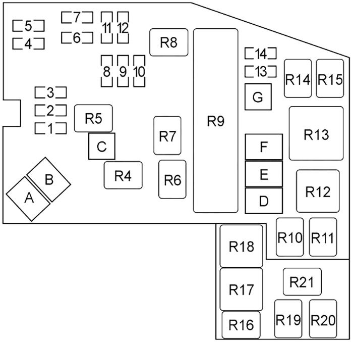
| № | A | Protected Component |
|---|---|---|
| 1 | - | - |
| 2 | 15 | Fog Light |
| 3 | 10 | Air Conditioning System |
| 4 | 10 | ECU Power Supply, Dome Light, Trunk Light, Ignition Key Hole Illumination Light, Meter, Gauge, MFI System, Vanity Mirror Light |
| 5 | 10 | Radio and Tape Player |
| 6 | 10 | Headlight (High Beam), Theft-Alarm System |
| 7 | 10 | Headlight (High Beam), Theft-Alarm System |
| 8 | 10 | Rheostat, Taillight, Position Light, Illumination Light |
| 9 | 10 | Taillight, Position Light, License Plate Light |
| 10 | - | - |
| 11 | 10 | Headlight (Low Beam) |
| 12 | 10 | Headlight (Low Beam) |
| 13 | 20 | INVECS-II 4A/T, MFI System, Air Conditioning System, Cooling System, Immobilizer System |
| 14 | 10 | Charging System, Central Door Locking System, Turn-Signal Light, Hazard Warning Light |
| A | 60 | Fuse (Passenger Compartment): "1", "2", "3", "10", "11" |
| B | - | - |
| C | 30 | Power Windows, Power Seat, Fuse (Passenger Compartment Fuse Box №2): "15", "17" |
| D | 50 | Air Conditioning System, Cooling System |
| E | 50 | Anti-lock Braking System (ABS) |
| F | - | - |
| G | 30 | Ignition Switch |
| R4 | Power Window | |
| R5 | Taillight | |
| R6 | Fog Light | |
| R7 | Headlight (High) | |
| R8 | Headlight (Low) | |
| R9 | Front-ECU | |
| R10 | ABS Warning Light | |
| R11 | Theft-Alarm Horn | |
| R12 | - | |
| R13 | Fan Control | |
| R14 | A/C Compressor | |
| R15 | Horn | |
| R16 | Inspection Connector | |
| R17 | - | |
| R18 | - | |
| R19 | A/T Control | |
| R20 | Fuel Pump | |
| R21 | MFI | |
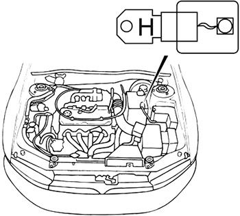
| № | A | Protected Component |
|---|---|---|
| H | 120 | Generator |
Advertisements
Advertisements