Advertisements
Fuse box diagram (fuse layout), location, and assignment of fuses MINI Cooper Countryman, Cooper S, John Cooper Works, One, One D & Cooper D (F60; 2017, 2018, 2019, 2020, 2021, 2022).

Checking and Replacing Fuses
The wiring circuits in the vehicle are protected from short circuits by fuses. This greatly reduces the chance of damage caused by electrical problems.
To check a fuse, look at the silver-colored band inside the fuse. If the band is broken or melted, replace the fuse.
Note
- Before replacing a fuse check that the key has been removed from the ignition and that all the services are switched off and/or disengaged.
- Incorrect and repaired fuses can overload electrical lines and components. There is a risk of fire. Never attempt to repair a blown fuse. Do not replace a nonworking fuse with a substitute of another color or amperage rating.
- The vehicle manufacturer recommends that you have a dealer’s service center or another qualified service center or repair shop replace the fuses.
- If a fuse blows again contact a qualified service center.
Passenger Compartment Fuse Box Diagram
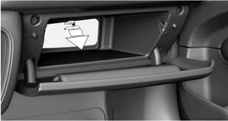
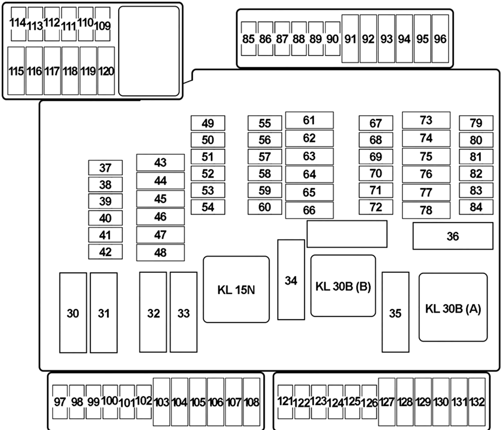
The fuses are located in the glove compartment. Open the glove compartment. Swing the cover down, arrow. Plastic tweezers and information on the fuse types and locations are stored in the fuse box.


| № | Amps | Protected Component |
|---|---|---|
| 30 | - | - |
| 31 | 50 | Heated Windscreen Relay |
| 32 | 40 | Body Domain Controller |
| 33 | - | - |
| 34 | 40 | Blower Output Stage |
| 35 | 50 | Body Domain Controller |
| 37 | 5 | Parking Brake Button |
| 38 | 5 | Siren with Tilt Alarm Sensor |
| 39 | 5 | Roof Function Centre (Airbag Indicator Lamp) |
| 40 | 5 | Dynamic Stability Control (DSC) |
| 41 | 5 | Instrument Cluster Control Unit |
| 42 | 5 | Remote Control Receiver (Comfort Access, Central Locking System, Tyre Pressure Control) |
| 43 | 30 | Roof Function Centre |
| 44 | 20 | Right Headlight |
| 45 | 30 | without Electromechanical Parking Brake: Dynamic Stability Control (DSC) |
| 40 | with Electromechanical Parking Brake: Dynamic Stability Control (DSC) | |
| 46 | 5 | except Cooper SE: Natural Vacuum Leak Detection |
| 10 | Cooper SE: Pressurised Fuel Tank Control Module | |
| 47 | 20 | Left Headlight |
| 48 | 30 | Selective Catalytic Reduction (SCR) Control Unit |
| 49 | 5 | Electrical Exhaust Flap, Control Electronics for Electric Auxiliary Heater №2 |
| 50 | 5 | Radiator Shutter Drive Unit, Environmental Air Catalyst Sensor (except Cooper SE) |
| 51 | 5 | Base Plate Fan |
| 52 | 5 | Electrochromic Interior Rear View Mirror |
| 53 | 5 | Automatic Recirculated Air Control (AUC) Sensor |
| 54 | 5 | Electromechanical Power Steering |
| 55 | 4 | Reversing Camera, Parking Assistant |
| 56 | 5 | except Cooper SE: Longitudinal Torque Distribution |
| Cooper SE: Longitudinal Torque Distribution, Vehicle Sound Generator 1 & 2 | ||
| 57 | - | - |
| 58 | 10 | Steering Column Switch Cluster |
| 59 | 5 | Camera-Based Driver Assistance System |
| 60 | 5 | Optional Extra System |
| 61 | 20 | Headunit (Radio or Navigation System) |
| 62 | 5 | Interior Light, Rain Light Solar Condensation Sensor, Vanity Mirror Light, Third Row of Seats Interior Light |
| 63 | 20 | Trailer Socket |
| 64 | - | - |
| 65 | 20 | Front Cigarette Lighter (12 V Power Socket) |
| 66 | 20 | Electric Fuel Pump Control Electronics |
| 67 | 5 | Exterior Mirror (Front Passenger) |
| 68 | 5 | Touchbox, Controller (CON), USB Hub, USB Charging Socket №3 |
| 69 | 5 | Exterior Mirror (Switch Block - Driver's Door) |
| 70 | 5 | Luggage Compartment Light, Glove Compartment Light, Rear Lid Button on Inside of Rear Lid |
| 71 | 7.5 | Instrument Cluster Control Unit |
| 72 | 5 | Fan 400W→: Electric Fan Cut-Out Relay |
| Fan →400W: Integrated Supply Module | ||
| 73 | 10 | Driver's Seat Backrest width Adjustment Valve Block, Driver Lumbar Support Valve Block, Switch for Backrest width Adjustment Driver's Seat |
| 74 | 7.5 | Petrol: Turbocharger Coolant Pump (TU) |
| 75 | 10 | Front Passenger Seat Backrest width Adjustment Valve Block, Front Passenger Lumbar Support Valve Block, Switch for Backrest width Adjustment Front Passenger |
| 76 | 10 | Diesel: Diesel Particulate Sensor |
| 77 | 10 | Nitrogen Oxide Sensor after Selective Catalytic Reduction (SCR) Catalytic Converter |
| 78 | 15 | Selective Catalytic Reduction (SCR) Control Unit |
| 79 | 5 | Base Plate, Wireless Charging Oddments Tray, Wireless Charging Oddments Tray Aerial Amplifier |
| 80 | 5 | Central Instrument, Central Information Display |
| 81 | 15 | Electronic Transmission Control |
| 82 | 5 | Selector Level |
| 83 | 7.5 | Petrol: Digital Motor Electronics |
| 84 | 5 | Clutch Module (Manual Transmission), Twin-Clutch Gearbox Control Unit, Twin-Clutch Gearbox Relay |
| 85 | 5 | Electrochromic Interior Rear View Mirror |
| 86 | - | - |
| 87 | - | - |
| 88 | - | - |
| 89 | - | - |
| 90 | - | - |
| 91 | 15 | Active Sound Design |
| 92 | 10 | Optional Extra System |
| 93 | - | - |
| 94 | - | - |
| 95 | 30 | Front Passenger Side Seat Adjustment Switch Block |
| 96 | 10 | Boot Lid/Tailgate Lock |
| 97 | - | - |
| 98 | 5 | Preparation of Tall Function |
| 99 | - | - |
| 100 | 5 | Cooper SE: High-Voltage Battery Unit |
| 101 | 5 | ID Reader, Car Sharing Module (CSM) |
| 102 | - | - |
| 103 | 20 | Right Headlight |
| 104 | 20 | Left Headlight |
| 105 | - | - |
| 106 | - | - |
| 107 | 40 | 2017: Automatic Luggage Compartment Lid Actuation |
| 2018-2022: Tailgate Function Module | ||
| 108 | - | - |
| 109 | 5 | Bi-Stable Relay |
| 110 | 5 | Bi-Stable Relay |
| 111 | 5 | Bi-Stable Relay |
| 112 | - | - |
| 113 | - | - |
| 114 | - | - |
| 115 | 5 | Cooper SE: Convenience Charging Electronics |
| 116 | - | - |
| 117 | - | - |
| 118 | - | - |
| 119 | 20 | Trailer Module, Trailer Socket |
| 120 | 20 | Trailer Module, Trailer Socket |
| 121 | 7.5 | USB Charging Socket №4 (Rear) |
| 122 | 5 | Safety Battery Terminal Gas Generator |
| 123 | 5 | Electrical A/C Compressor, Electric Auxiliary Heater |
| 124 | 10 | Cooper SE: Electric-Machine Electronics |
| 125 | - | - |
| 126 | - | - |
| 127 | 30 | Driver's Seat Heating Electronics (Basic Version), Driver's Seat Module (High Version) |
| 128 | 30 | Front Passenger Seat Heating Electronics |
| 129 | 30 | HiFi Amplifier |
| 130 | 10 | Cooper SE: Coolant Pump 2 in Low-Temperature Coolant Circuit |
| 131 | 30 | except Cooper SE: Longitudinal Torque Distribution |
| Cooper SE: Transmission Oil Pump, Longitudinal Torque Distribution | ||
| 132 | 20 | 12 V Power Socket №1, 12 V Power Socket №2 (2017-2018), 12 V Power Socket №4 (Luggage) |
Advertisements
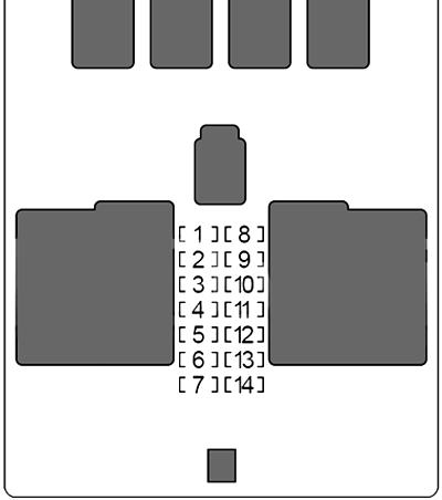
BDC (Body Domain Controller)
It is located in the front passenger’s footwell.


| № | Amps | Protected Component |
|---|---|---|
| 1 | 30 | Passenger Power Window |
| 2 | 30 | Rear Driver's Side Power Window |
| 3 | 20 | Front Passenger Door Lock |
| 4 | 30 | Driver Power Window |
| 5 | 30 | Rear Window Defogger |
| 6 | 30 | Rear Passenger Side Power Window |
| 7 | 20 | Driver's Door Lock |
| 8 | - | - |
| 9 | 5 | Light Operating Unit, Steering Column Switch Cluster, Driver Assistance System Operating Facility with Hazard Warning Switch |
| 10 | 7.5 | Diagnosis Socket |
| 11 | 7.5 | Heating/Air Conditioning System, Tailgate Function Module |
| 12 | 5 | Evaluation Electronics for Contact-Free Tailgate Opening, Telematic Communication Box, Electronic Outer Door Handle Module (Driver/Passenger) |
| 13 | 15 | Horn |
| 14 | 15 | Rear Wiper & Washer |
Advertisements
