
Advertisements
Fuse box diagram (fuse layout), location, and assignment of fuses and relays Mercury Sable G, GS and LS (1996, 1997, 1998, 1999).
Checking and Replacing Fuses
Fuses and circuit breakers protect your vehicle’s electrical system from overloading. If electrical components in the vehicle are not working, the system may have been overloaded and blown a fuse or tripped a circuit breaker. Check the appropriate fuses before replacing any electrical components. A blown fuse can be identified by a break in the wire within the fuse.
Notice
- Before replacing a fuse check that the key has been removed from the ignition and that all the services are switched off and/or disengaged.
- Always disconnect the battery before servicing high current fuses.
- Do not repair fuses and never replace a blown fuse with one that has a higher amp rating. This can severe wire damage and could start a fire.
- Never replace a broken fuse with anything other than a new fuse.
- Even after a fuse is replaced, it will continue to blow if the cause of the overload is not identified and corrected. If the fuse continues to blow, have the vehicle’s electrical system checked by your dealer or a qualified service technician.
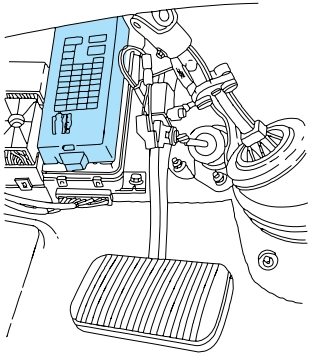
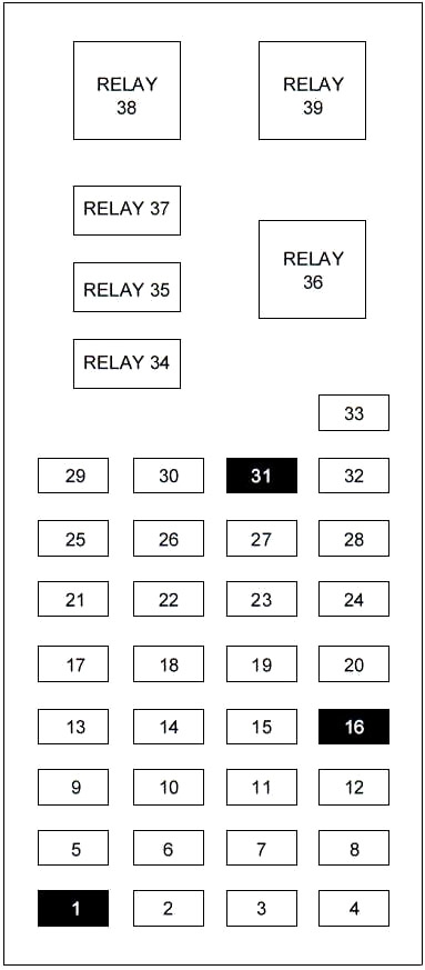
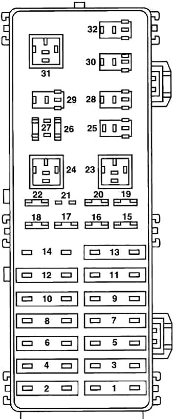
Passenger Compartment Fuse Box
The fuse panel is located below and to the left of the steering wheel by the brake pedal. Remove the panel cover to access the fuses. To remove a fuse use the fuse puller tool provided on the fuse panel cover.
| № | A | Description |
|---|---|---|
| 1 | — | Not Used |
| 2 | 5 | Instrument Illumination |
| 3 | 10 | Left Low Beam Headlamp |
| 4 | 10 | Right Low Beam Headlamp |
| 5 | 5 | Instrument Cluster, Shift Lock Actuator, Rear Defrost |
| 6 | 15 | TR Sensor, Reverse Lamps, Daytime Running Lamps, A/C Controls, MLPS switch, Speed Control |
| 7 | 10 | TR Sensor, Starter Relay, MLPS switch |
| 8 | 5 | Power Antenna, Radio Control Unit, GEM |
| 9 | 10 | ABS, Central Temperature Monitor |
| 10 | 20 | PCM Relay, Ignition Coil, Radio, Passive Anti-Theft System |
| 11 | 5 | Instrument Cluster, Air Bag Indicator |
| 12 | 5 | Instrument Cluster, Autolamps, Transmission Control Switch, Integrated Control Panel, GEM |
| 13 | 5 | Electronic Crash Unit (ECU), Blower Motor, Air bag, Electronic Automatic Temperature Control |
| 14 | 5 | Air Suspension, Lamp Outage Indication (1996-1997) |
| 15 | 10 | Multifunction Switch (Turn Signal) |
| 16 | — | Not Used |
| 17 | 30 | Front Wiper/Washer |
| 18 | 5 | Headlamp Switch |
| 19 | 15 | Rear Wiper/Washer |
| 20 | 5 | Integrated Control Panel, Remote Entry, Phone, GEM (1999) |
| 21 | 20 | Cigar Lighter |
| 22 | 5 | Power Mirrors, Power Antenna, Luggage Compartment Lamp, Autolamp |
| 23 | 5 | GEM, Wiper system, Variable Assist Steering, Remote Entry, Anti-Theft |
| 24 | 5 | RCC, Speedometer, Integrated Control Panel, Electronic Automatic Temperature Control Module |
| 25 | 10 | Data Link Connector (DLC) |
| 26 | 15 | Luggage Compartment |
| 27 | 10 | Battery Saver Relay |
| 28 | 15 | Speed Control, Brake Lamp |
| 29 | 15 | Multifunction Switch, Hazard |
| 30 | 15 | High Beams, Daytime Running Lamps, Instrument Cluster |
| 31 | 5 | Tail Lamp Feed |
| 32 | 5 | 1996: Integrated Control Panel, Heated Mirrors |
| 10 | 1997-1999: Integrated Control Panel, Climate Controls, Heated Mirrors | |
| 33 | 5 | Power Windows, Lock Illumination |
| 34 | Battery Saver Relay | |
| 35 | Driver Door Unlock Relay | |
| 36 | Rear Defroster Relay | |
| 37 | Interior Lamp Relay | |
| 38 | One Touch Window Down Relay | |
| 39 | Accessory Delay Relay | |
Advertisements
Engine Compartment Fuse Box
The power distribution box is located in the engine compartment. The power distribution box contains high current fuses that protect your vehicle’s main electrical systems from overloads.
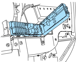
Diagram 1996
| № | A | Description |
|---|---|---|
| 1 | 40 | Junction block |
| 2 | 30 | EEC power |
| 3 | 40 | Ignition |
| 4 | 30 | Power locks |
| 5 | 40 | Ignition |
| 6 | 30 | Power seats |
| 7 | 40 | Rear window defrost |
| 8 | 30 | Thermactor pump |
| 9 | 40 | Cooling fan |
| 10 | 20 | Fuel pump |
| 11 | 40 | Blower motor |
| 12 | 20 | Semi-active suspension |
| 13 | 40 | ABS module |
| 14 | 20 | Radio |
| 15 | 15 | Datime running lamps |
| 16 | 10 | Air bag |
| 17 | 20 | Radio |
| 18 | 30 | Headlamps |
| 19 | 15 | Horn |
| 20 | 15 | Park lamps |
| 21 | - | Not used |
| 22 | 30 | Headlamps |
| 26 | 30 | Alternator |
| 27 | 10 | Hego power |
| 23 | Blower motor relay | |
| 24 | Wiper park relay | |
| 25 | Wiper hi/lo relay | |
| 28 | Washer motor relay | |
| 29 | Horn relay | |
| 30 | Autolamp headlamp relay | |
| 31 | Starter relay | |
| 32 | Autolamp park relay | |
Diagram 1997-1999
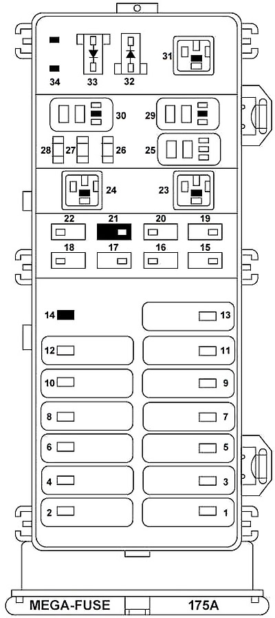
| № | A | Description |
|---|---|---|
| 1 | 40 | Fuse Junction Panel |
| 2 | 30 | PCM Relay |
| 3 | 40 | Ignition Switch, Starter Relay |
| 4 | 30 | Circuit Breaker: Accessory Delay Relay, Power Windows, Left/Right Power Seats |
| 5 | 40 | Ignition Switch |
| 6 | 30 | 1997-1998: Left/Right Power Seats |
| 1998-1999: Not Used | ||
| 7 | 40 | Rear Window Defrost Relay |
| 8 | 30 | Thermactor Air ByPass Solenoid, EAM Solid State Relay |
| 9 | 40 | High Speed Cooling Fan Relay, Low Speed Cooling Fan Relay |
| 10 | 20 | Fuel Pump Relay |
| 11 | 40 | Blower Motor Relay |
| 12 | — | Not Used |
| 13 | 40 | Anti-Lock Brake Module |
| 14 | — | Not Used |
| 15 | 15 | Daytime Running Lamps (DRL) Module |
| 16 | 10 | 1997-1998: Air Bag Diagnostic Monitor |
| 1999: Electronic Control Unit (ECU) | ||
| 17 | 20 | Rear Control Unit, CD Changer |
| 18 | 30 | Anti-Lock Brake Module |
| 19 | 15 | Horn Relay, Powertrain Control Module (PCM) |
| 20 | 15 | Headlamp Switch, Autolamp Park Relay |
| 21 | — | Not Used |
| 22 | 30 | Autolamps Relay, Multifunction Switch, Headlamp Switch |
| 25 | — | A/C Clutch Relay |
| 26 | 30 | Generator/Voltage Regulator |
| 27 | 10 | A/C Clutch Relay |
| 28 | 15 | Heated Oxygen Sensors, Canister Vent |
| 32 | PCM Diode | |
| 33 | A/C Clutch Diode | |
| 34 | Not Used | |
| 23 | Blower Motor Relay | |
| 24 | Starter Relay | |
| 29 | Fuel Pump Relay | |
| 30 | PCM Relay | |
| 31 | Low Speed Cooling Fan Relay | |
Advertisements