
Advertisements
Fuse box diagram (fuse layout), location, and assignment of fuses and relays Mercury Mariner (2005, 2006, 2007).
Checking and Replacing Fuses
Fuses and circuit breakers protect your vehicle’s electrical system from overloading. If electrical components in the vehicle are not working, the system may have been overloaded and blown a fuse or tripped a circuit breaker. Check the appropriate fuses before replacing any electrical components. A blown fuse can be identified by a break in the wire within the fuse.
Notice
- Before replacing a fuse check that the key has been removed from the ignition and that all the services are switched off and/or disengaged.
- Always disconnect the battery before servicing high current fuses.
- Do not repair fuses and never replace a blown fuse with one that has a higher amp rating. This can severe wire damage and could start a fire.
- Never replace a broken fuse with anything other than a new fuse.
- Even after a fuse is replaced, it will continue to blow if the cause of the overload is not identified and corrected. If the fuse continues to blow, have the vehicle’s electrical system checked by your dealer or a qualified service technician.
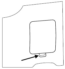
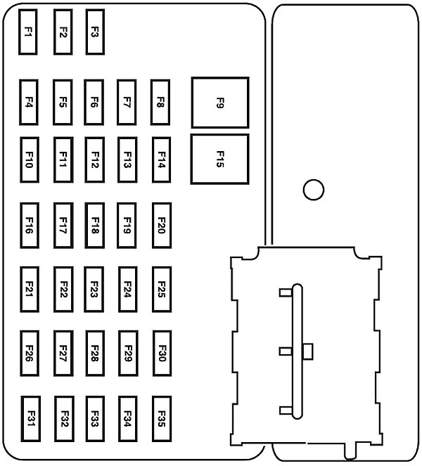
Passenger Compartment Fuse Box
The fuse panel is located on the right-hand side of the center console, by the instrument panel. Remove the panel cover to access the fuses.
| № | A | Protected components |
|---|---|---|
| 1 | 15 | Trailer tow park lamps |
| 2 | - | - |
| 3 | 15 | Front and rear park lamps |
| 4 | 10 | Ignition switch |
| 5 | 2 | Powertrain Control Module (PCM relay), Fuel pump relay, Main fan relay, High/Low speed fan relay 2, PATS module |
| 6 | 15 | Center High-Mounted Stop Lamp (CHMSL), Stop lamps, PCM, Anti-lock Brake System (ABS), Speed control, Brake On-Off switch |
| 7 | 10 | Instrument cluster, Diagnostic connector, Power mirror switch, Radio |
| 8 | 5 | Canister vent (2007) |
| 9 | 30 | Power door locks, Power seats |
| 10 | 15 | Heated mirrors |
| 11 | 15 | Sunroof, Electrochromatic mirror, Compass |
| 12 | 5 | Radio |
| 13 | - | - |
| 14 | - | - |
| 15 | 30 | Power windows |
| 16 | 15 | Subwoofer |
| 17 | 15 | Low beams |
| 18 | 10 | 4WD |
| 19 | - | - |
| 20 | 15 | Horn |
| 21 | 10 | 2005-2006: Rear wiper motor, Rear wiper washer |
| 15 | 2007: Rear wiper motor, Rear wiper washer | |
| 22 | 10 | Instrument cluster |
| 23 | - | - |
| 24 | 20 | Cigar lighter |
| 25 | 20 | Front wiper motor, Front wiper washer |
| 26 | 5 | Climate control system mode switch |
| 27 | 5 | Canister vent (2005-2006), Speed control cancel switch |
| 28 | 10 | Instrument cluster |
| 29 | 10 | Reverse park aid |
| 30 | - | - |
| 31 | - | - |
| 32 | 10 | Brake-Transmission shift lock |
| 33 | 15 | Air bag module, Passenger Air bag Deactivation (PAD) indicator lamp, Occupant Classification Sensor (OCS) |
| 34 | 5 | ABS module, Evac and Fill, Speed control |
| 35 | 5 | Heated seats module, 4WD |
Advertisements
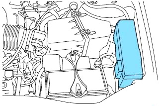
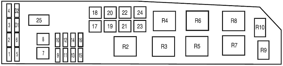
Engine Compartment Fuse Box
The power distribution box is located on the driver’s side of the engine compartment. The power distribution box contains high-current fuses that protect your vehicle’s main electrical systems from overloads.
| № | A | Protected components |
|---|---|---|
| 1 | - | - |
| 2 | 25 | Headlamp power |
| 3 | 25 | High beams, Turn signals, Interior lamps, Headlamp power |
| 4 | 5 | Keep Alive Power (KA PWR) |
| 5 | 15 | Heated Exhaust Gas Oxygen (HEGO) sensors |
| 6 | 20 | Fuel pump |
| 7 | 40 | RUN/ACC relay - Electrochromatic mirror, Cigar lighter, Front and rear wipers, Compass |
| 8 | 30 | Powertrain Control Module (PCM), Injectors and coil |
| 9 | 15 | Alternator |
| 10 | 30 | Heated seats |
| 11 | 10 | PCM |
| 12 | 20 | Power point |
| 13 | 20 | Fog lamps |
| 14 | 15 | A/C clutch, A/C relay |
| 15 | 30 | Anti-lock Brake System (ABS) solenoid |
| 16 | 25 | I/P fuse panel (RUN/START) |
| 17 | 50 | Ignition (main) |
| 18 | 40 | Blower motor |
| 19 | 40 | Accessory delay relay - Subwoofer and 4WD, Low beam |
| 20 | 60 | ABS |
| 21 | 40 | Horn, CHMSL, Cluster, Power locks and power seats |
| 22 | 40 | 2.3 L: Cooling fan |
| 50 | 3.0 L: Cooling fan | |
| 23 | 40 | Rear defroster, Park lamps relay |
| 24 | 40 | 2.3 L: High/Low speed fan |
| 50 | 3.0 L: High/Low speed fan | |
| 25 | - | Shunt |
| R2 | PCM | |
| R3 | Fuel pump | |
| R4 | Cooling fan | |
| R5 | High/Low speed fan 1 | |
| R6 | Blower motor | |
| R7 | Starter | |
| R8 | High/Low speed fan 2 | |
| R9 | Fog lamps | |
| R10 | A/C | |
| D1 | - | |
| D2 | A/C diode | |
Advertisements