
Advertisements
Fuse box diagram (fuse layout), location, and assignment of fuses and relays Mercedes-Benz Vaneo (W414) (2001, 2002, 2003, 2004, 2005).
Checking and Replacing Fuses
The fuses in your vehicle serve to close down faulty circuits. If a fuse blows, all the components on the circuit and their functions stop operating. If a fuse has blown, the inside element will be melted. Blown fuses must be replaced with fuses of the same rating, which you can recognize by the color and value. The fuse ratings are listed in the fuse allocation chart.
If a newly inserted fuse also blows, have the cause traced and rectified at a qualified specialist workshop, e.g. an authorized Mercedes-Benz Center.
Notice
- Before changing a fuse, secure the vehicle against rolling away and switch off all electrical consumers.
- Always disconnect the battery before servicing high current fuses.
- Always replace faulty fuses with the specified new fuses having the correct amperage. If you manipulate or bridge a faulty fuse or if you replace it with a fuse with a higher amperage, the electric cables could be overloaded. This could result in a fire. There is a risk of an accident and injury.
- Only use fuses that have been approved for Mercedes-Benz vehicles and which have the correct fuse rating for the system concerned. Otherwise, components or systems could be damaged.
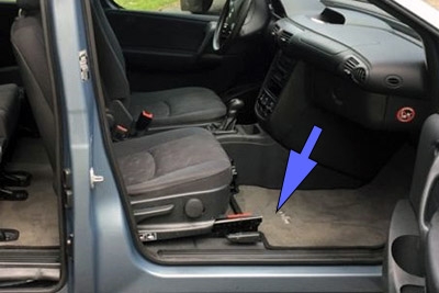
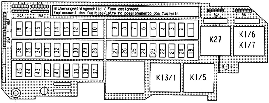
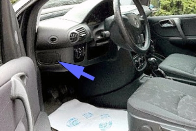
Passenger Compartment Fuse Box
The main fuse box is located near the battery under the floor panel in front of the front left seat.
| № | Fused function | A |
|---|---|---|
| 1 | Electric extractor fan control unit* | 20 |
| Electric extractor fan relay | ||
| Engine control unit | ||
| Air injection relay (gasoline) | ||
| 2 | Engine control unit | 25 |
| Fuel pump relay (gasoline) | ||
| 3 | Heating/Tempmatic control panel | 25 |
| Interior blower | ||
| 4 | Electronic Stability Program control unit | 7.5 |
| Brake pedal switch | ||
| 5 | Automatic transmission control unit* | 10 |
| Cruise control switch* | ||
| Automatic clutch* | ||
| 6 | Horn | 15 |
| 7 | Brake lamp | 10 |
| 8 | Diagnostic socket | 10 |
| Heating/Tempmatic control panel | ||
| 9 | Electric extractor fan control unit* | 30 |
| Electric extractor fan relay | 40 | |
| 10 | Sliding/tilting sunroof | 15 |
| Rear window wiper | ||
| 11 | Centre ceiling lamps - spotlight and nightlight* | 15 |
| Radio Navigations System* | ||
| Telephone hands-free device* | ||
| Headlamp flasher | ||
| 12 | Cigarette lighter | 20 |
| Glove compartment light | ||
| 12 V load compartment socket* | ||
| 13 | Left-hand power window | 30 |
| Left-hand convenience power window (Automatic opening/closing)* | 7.5 | |
| 14 | Right-hand power window | 30 |
| Right-hand convenience power window (Automatic opening/closing)* | 7.5 | |
| 15 | Seat occupancy recognition including child seat recognition | 7.5 |
| Automatic child seat recognition | ||
| Airbag control unit | ||
| 16 | Windscreen wiper motor | 30 |
| 17 | Windscreen washer fluid pomp | 10 |
| Central locking (Diagnostic) | ||
| Instrument cluster (Control of front/rear windscreen wipers and intermittent wipe interval, wiper/washer system, heated rear window and mirror heating, airbag indicator lamp) | ||
| 18 | 12 V centre console socket | 25 |
| 19 | Trailer socket* | 15 |
| Taxi alarm control unit* | ||
| 20 | Trailer recognition control unit* | 7.5 |
| Taxi alarm control unit* | ||
| 21 | Trailer recognition control unit* | 15 |
| 22 | Anti-theft alarm system control unit* | 10 |
| Alarm siren* | ||
| 23 | Seat heating | 25 |
| 24 | 40 | |
| 25 | Right-hand convenience power window (Automatic opening/closing)* | 30 |
| 26 | Left-hand convenience power window (Automatic opening/closing)* | 30 |
| 27 | Auxiliary heating time control unit* | 5 |
| Auxiliary heating radio receiver* | ||
| Illuminated door sill panels* | ||
| 28 | Instrument cluster (Turn signal operation, wiper/washer system, heated rear window ) | 10 |
| Taxi meter* | ||
| Taxi roof sign* | ||
| 29 | Central locking | 25 |
| 30 | Drive authorisation system control unit | 7.5 |
| Instrument cluster (indic. lamp. Turn signal operation. interior lighting) | ||
| Steering angle sensor | ||
| 31 | Heated rear window (Mirror heating) | 25 |
| 32 | HF telephone compensator* | 15 |
| Telephone hands-free device* | ||
| Sliding/tilting sunroof* | ||
| Centre and rear celling lamps-overhead* | ||
| Control panel with front interior light* | ||
| Taxi alarm control unit* | ||
| 33 | Radio / navigation* | 20 |
| Hands-free system selector switch* | ||
| Telephone / taxi radio* | ||
| Taxi radio control unit* | ||
| 34 | Fuel pump (gasoline) | 25 |
| 35 | Valves for Electronic Stability Program | 25 |
| 36 | Lamp unit | 40 |
| 37 | Mirror heating | 10 |
| 38 | Starter relay (diesel) | 30 |
| Engine control unit (gasoline) | 7.5 | |
| 39 | Drive authorisation system control unit | 7.5 |
| Instrument cluster (indic. lamp. Turn signal operation) | ||
| 40 | Diagnostic socket | 7.5 |
| Steering angle sensor | ||
| Mirror adjustment | ||
| 41 | Level 2 interior blower* | 7.5 |
| PTC - diesel heater booster | ||
| Heating/Tempmatic control panel | ||
| Dew point sensor (air conditioning)* | ||
| Heated washer nozzles | ||
| Interior temp. sensor (air conditioning)* | ||
| Folding exterior mirror* | ||
| 42 | Lamp unit | 7.5 |
| Reversing lamp (manual transmission) | ||
| Electronic selector lever module* | ||
| 43 | Reversing lamp (autom. transmission) | 7.5 |
| Taximeter* | ||
| 44 | Auxiliary heating time control* | 7.5 |
| Parktronic control unit* | ||
| 45 | Electric hinged window* | 7.5 |
| K1/6 | Terminal 87 engine control unit relay (A 002 542 25 19) | |
| K1/7 | ||
| K1/5 | Fuel pump relay (A 002 542 25 19) | |
| K13/1 | Terminal 15 electronics relay (A 002 542 13 19) | |
| K27 | Heated rear window relay (A 002 542 13 19) | |
| * Optional | ||
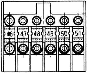
Prefuse box
It is on the battery’s positive terminal.
| № | Fused function | A |
|---|---|---|
| 46 | Terminal connector, terminal 30 | 150 |
| Supply to fueee f4, f5, f6 via relay K1/5 | ||
| Supply to fuses f1, f2 via relay K1/6, K1/7 | ||
| Alternator | ||
| Supply to fuses f19, f20, f21 | ||
| PTC heater booster (diesel) | ||
| 47 | Preglow phase (diesel) | 60 |
| Air injection (petrol) | 40 | |
| 48 | Power-steering pump | 60 |
| 49 | Return pump | 40 |
| Electronic Stability Program | ||
| 50 | Ignition starter switch | 50 |
| 51 | Auxiliary heating | 30 |
Advertisements
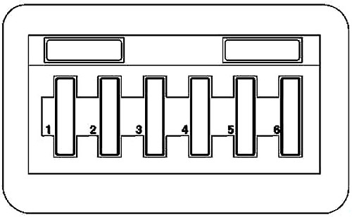
Instrument Panel Fuse Box
The light module fuse box is on the left side of the instrument panel.
| № | Fused function | A |
|---|---|---|
| 1 | Left low beam | 7.5 |
| 2 | Right low beam | 7.5 |
| 3 | Left main beam | 15 |
| Right main beam | ||
| Main beam indicator lamp (instrument cluster) | ||
| 4 | Left side lamp | 7.5 |
| Left tail lamp | ||
| 5 | Right side lamp | 15 |
| Right tail lamp | ||
| 58K instrument cluster | ||
| License plate lamps | ||
| 6 | Left/right fog lamp | 15 |
| Left rear fog lamp |
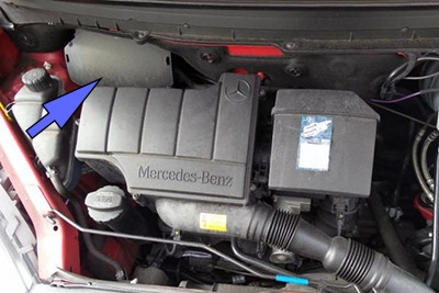
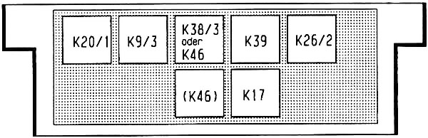
Control Module Box
It is in the engine compartment.
| № | Relay |
|---|---|
| K20/1 | High-pressure return relay (A 002 542 13 19) |
| K9/3 | Electric extractor fan relay (A 002 542 13 19) |
| K38/3 | Starter inhibitor relay (A 002 542 23 19) |
| K46 | Alarm relay (A 002 542 14 19) |
| K39 | Horn relay (A 002 542 11 19) |
| K26/2 | Washer pump relay (A 002 542 19 19) |
| K17 | Air injection relay (A 002 542 13 19) |
Advertisements