
Advertisements
Fuse box diagram (fuse layout), location, and assignment of fuses and relays Mercedes-Benz SLS AMG (Coupe C197 and Roadster R197) (2010, 2011, 2012, 2013, 2014, 2015).

Checking and Replacing Fuses
The fuses in your vehicle serve to close down faulty circuits. If a fuse blows, all the components on the circuit and their functions stop operating. If a fuse has blown, the inside element will be melted. Blown fuses must be replaced with fuses of the same rating, which you can recognize by the color and value. The fuse ratings are listed in the fuse allocation chart (it is located with the wheel-change toolkit in the trunk).
If a newly inserted fuse also blows, have the cause traced and rectified at a qualified specialist workshop, e.g. an authorized Mercedes-Benz Center.
Notice
- Before changing a fuse, secure the vehicle against rolling away and switch off all electrical consumers.
- Always disconnect the battery before servicing high current fuses.
- Always replace faulty fuses with the specified new fuses having the correct amperage. If you manipulate or bridge a faulty fuse or if you replace it with a fuse with a higher amperage, the electric cables could be overloaded. This could result in a fire. There is a risk of an accident and injury.
- Only use fuses that have been approved for Mercedes-Benz vehicles and which have the correct fuse rating for the system concerned. Otherwise, components or systems could be damaged.
Location
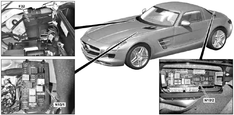
- F32 – Front electrical prefuse box
- N10/1 – Front SAM control unit with fuse
- N10/2 – Rear SAM control unit with fuse and relay module and relay module
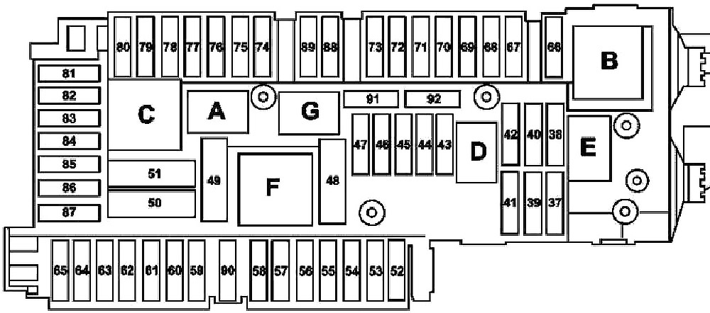
Passenger Compartment Fuse Box
The fuse block is located in the footwell on the front passenger side.
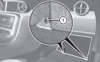
- To open: remove the carpet over the footrest.
- Loosen screws (1) on the floor panel using a suitable tool.
- Remove the floor panel.
- To close: install the floor panel again.
- Screw-in and tighten screws (1).
- Put in the carpet and press to secure.
Advertisements
| № | Fused function | A |
|---|---|---|
| 37 | Reserve | - |
| 38 | Reserve | - |
| 39 | Coupe: Charging socket electrical connection | 15 |
| Roadster: Control unit for soft top control | ||
| 40 | Reserve | - |
| 41 | Electric parking brake controller unit | 30 |
| 42 | Left fuel pump fuel system control unit | 25 |
| 43 | Reserve | - |
| 44 | Reserve | - |
| 45 | Reserve | - |
| 46 | M 1, AM, CL antenna amplifier | 7.5 |
| M 2 and DAB antenna amplifier | ||
| Alarm siren (USA version; up to 30.9.10 and as of 1.10.10) | ||
| Interior protection and tow-away protection control unit | ||
| 47 | Reserve | - |
| 48 | Reserve | - |
| 49 | Rear window heater | 40 |
| 50 | Sound system amplifier control unit (advanced sound system) | 30 |
| 51 | Rear bass speaker amplifier (advanced sound system) | 40 |
| 52 | Reserve | - |
| 53 | Reserve | - |
| 54 | Reserve | - |
| 55 | Left fuel pump fuel system control unit | 5 |
| 56 | Reversing camera | 5 |
| 57 | Reserve | - |
| 58 | Roadster: Control unit for soft top control | 15 |
| Black Series: Electric differential lock control unit | ||
| 59 | Blind Spot Assist: | 5 |
| Left rear bumper intelligent radar sensor | ||
| Right rear bumper intelligent radar sensor | ||
| 60 | Roadster: Control unit for soft top control | 25 |
| 61 | as of 1.6.11: | 7.5 |
| Router relay | ||
| AMG Performance Media control unit | ||
| 62 | Driver seat control unit | 30 |
| 63 | Reserve | - |
| 64 | Front passenger seat control unit | 30 |
| 65 | Adaptive damping system control unit (AMG RIDE CONTROL sports suspension) | 10 |
| 66 | Reserve | - |
| 67 | Roadster: Control unit for soft top control | 40 |
| 68 | Roadster: AIRSCARF control unit | 25 |
| 69 | Roadster: AIRSCARF control unit | 25 |
| 70 | Tire pressure monitor control unit | 5 |
| 71 | Front vehicle interior power outlet (front cigarette lighter with ashtray illumination) | 15 |
| 72 | Reserve | - |
| 73 | Transmission mode control unit | 5 |
| 74 | KEYLESS-GO control unit | 15 |
| 75 | Circuit 30 connector sleeve, KEYLESS-GO door handle function | 20 |
| 76 | Reserve | - |
| 77 | USA version: Weight Sensing System (WSS), control unit | 7.5 |
| 78 | Media interface control unit | 7.5 |
| 79 | Driver seat connector block | 7.5 |
| Front passenger seat connector block | ||
| 80 | PARKTRONIC control unit | 5 |
| 81 | Mobile phone electrical connection | 5 |
| 82 | Rear spoiler motor relay, raise | 10 |
| Rear spoiler motor relay, lower | ||
| 83 | Emergency call system control unit | 7.5 |
| Japanese version: Electronic Toll Collection control unit | ||
| 84 | Satellite digital audio radio (SDAR) control unit | 7.5 |
| Digital Audio Broadcasting control unit | ||
| 85 | Reserve | - |
| 86 | Reserve | - |
| 87 | Emergency call system control unit | 7.5 |
| 88 | Dual clutch transmission control unit | 15 |
| 89 | Reserve | - |
| 90 | Reserve | - |
| A | Circuit 15 relay | |
| B | Circuit 15R relay (1) | |
| C | Rear window heater relay | |
| D | Fuel pump relay | |
| E | Reserve | |
| Seat adjustment relay | ||
| G | Circuit 15R relay (2) | |
Front prefuse box
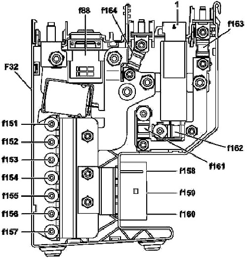
| № | Fused function | A |
|---|---|---|
| 88 | Pyrofuse 88 | 400 |
| 151 | Internal combustion engine and air conditioning fan motor with integrated control | 100 |
| 152 | Front SAM control module with fuse and relay module | 150 |
| 153 | Reserve | - |
| 154 | Front SAM control module with fuse and relay module | 60 |
| 155 | Reserve | - |
| 156 | Reserve | - |
| 157 | Reserve | - |
| 158 | Reserve | - |
| 159 | Reserve | - |
| 160 | Blower regulator | 60 |
| 161 | Front SAM control module with fuse and relay module | 100 |
| 162 | Reserve | - |
| 163 | Rear SAM control unit with fuse and relay module | 150 |
| 164 | Rear SAM control unit with fuse and relay module | 150 |
Advertisements
Luggage Compartment Fuse Box
Coupe
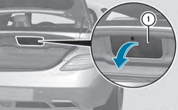
- To open: open the trunk.
- Fold cover (1) in the center of the rear wall down in the direction of the arrow.
- To close: fold cover (1) up in the opposite direction to the arrow and press to secure.
Roadster
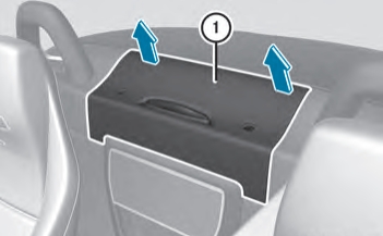
- To open: from the vehicle interior, lift up cover (1) between the roll bars in the direction of the arrow.
- To close: shut cover (1) in the opposite direction to the arrow and press to secure.
The cover must be installed properly, otherwise, moisture or dirt could impair the function of the fuses.
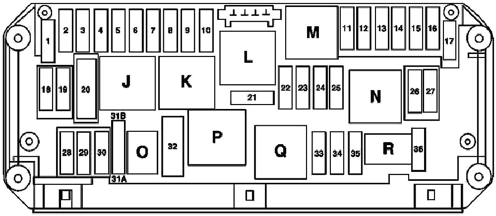
| № | Fused function | A |
|---|---|---|
| 1 | Electronic Stability Program control unit | 25 |
| 2 | Left door control unit | 30 |
| 3 | Right right door control unit | 30 |
| 4 | Reserve | - |
| 5 | Instrument cluster | 7.5 |
| Rear SAM control unit with fuse and relay module | ||
| Adaptive damping system control unit (AMG RIDE CONTROL sports suspension) | ||
| 6 | ME-SFI [ME] control unit | 7.5 |
| 7 | Starter | 20 |
| 8 | Supplemental restraint system control unit | 7.5 |
| 9 | Glove compartment socket | 15 |
| 10 | Master windshield wiper motor | 30 |
| Slave windshield wiper motor | ||
| 11 | COMAND display | 7.5 |
| 12 | Audio/COMAND control panel | 7.5 |
| AAC control and operating unit | ||
| Upper control panel control unit | ||
| 13 | Steering column tube module control unit | 7.5 |
| 14 | Electronic Stability Program control unit | 7.5 |
| 15 | Supplemental restraint system control unit | 7.5 |
| 16 | Diagnostic connector | 5 |
| DIRECT SELECT INTERFACE | ||
| 17 | Oil cooler fan motor | 15 |
| 18 | Reserve | - |
| 19 | Reserve | - |
| 20 | Electronic Stability Program control unit | 40 |
| 21 | Brake lights switch | 7.5 |
| Glove compartment lamp over glove compartment lamp switch | ||
| Front passenger seat occupied recognition and ACSR [AKSE] (USA version) | ||
| 22 | Oil sensor (oil level, temperature and quality) | 15 |
| Internal combustion engine and air conditioning fan motor with integrated control | ||
| Connector sleeve, circuit 87 M2e | ||
| Interior and engine wiring harness electrical connection (pin 5) | ||
| 23 | Fused through circuit 87 M1 e connector sleeve: | 25 |
| Interior and engine wiring harness electrical connector (pin 4) | ||
| Starter circuit 50 relay | ||
| Oil cooler fan motor relay | ||
| ME-SFI [ME] control unit | ||
| 24 | Purging switchover valve | 15 |
| Interior and engine wiring harness electrical connector (pin 8) | ||
| 25 | Coolant circulation pump | 15 |
| ME-SFI [ME] control unit | ||
| Activated charcoal canister shutoff valve (USA version) | ||
| 26 | COMAND controller unit | 20 |
| 27 | ME-SFI [ME] control unit | 7.5 |
| Electronic ignition lock control unit | ||
| 28 | Instrument cluster | 7.5 |
| 29 | Reserve | - |
| 30 | Reserve | - |
| 31A | Left horn | 15 |
| Right horn | ||
| 31B | Left horn | 15 |
| Right horn | ||
| 32 | Electric air pump | 40 |
| 33 | Reserve | - |
| 34 | Reserve | - |
| 35 | Reserve | - |
| 36 | Electric parking brake controller unit | 7.5 |
| J | Circuit 15 relay | |
| K | Circuit 15R relay | |
| L | Reserve relay | |
| M | Starter circuit 50 relay | |
| N | Engine circuit 87 relay | |
| O | Horn relay | |
| P | Secondary air injection relay | |
| Q | Oil cooler fan motor relay | |
| R | Chassis circuit 87 relay | |
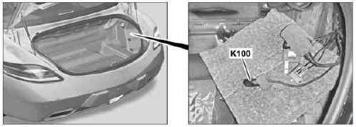
Router Relay
(AMG Performance Media as of 01.06.2011)
Advertisements