
Advertisements
Fuse box diagram (fuse layout), location, and assignment of fuses and relays Mercedes-Benz S-Class (W222, C217, A217) (S300, S320, S350, S400, S450, S500, S560, S600, S63 AMG, S65, Hybrid) (2014, 2015, 2016, 2017, 2018).

Checking and Replacing Fuses
The fuses in your vehicle serve to close down faulty circuits. If a fuse blows, all the components on the circuit and their functions stop operating. If a fuse has blown, the inside element will be melted. Blown fuses must be replaced with fuses of the same rating, which you can recognize by the color and value. The fuse ratings are listed in the fuse allocation chart (located in a recess at the side of the fuse box in the trunk).
If a newly inserted fuse also blows, have the cause traced and rectified at a qualified specialist workshop, e.g. an authorized Mercedes-Benz Center.
Notice
- Before changing a fuse, secure the vehicle against rolling away and switch off all electrical consumers.
- Always disconnect the battery before servicing high current fuses.
- Always replace faulty fuses with the specified new fuses having the correct amperage. If you manipulate or bridge a faulty fuse or if you replace it with a fuse with a higher amperage, the electric cables could be overloaded. This could result in a fire. There is a risk of an accident and injury.
- Only use fuses that have been approved for Mercedes-Benz vehicles and which have the correct fuse rating for the system concerned. Otherwise, components or systems could be damaged.
Location
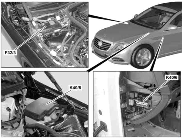
- F32/3 – Engine compartment prefuse box
- K40/6 – Left fuse and relay module
- K40/8 – Engine fuse and relay module
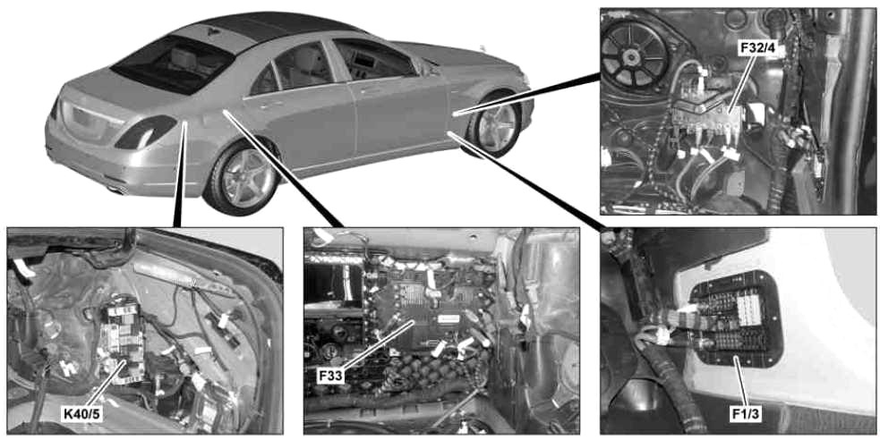
- F1/3 – Right A-pillar fuse box
- F32/4 – Vehicle interior prefuse box
- F33 – Rear prefuse box
- K40/5 – Rear fuse and relay module
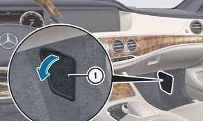
Instrument Panel Fuse Box
The fuse panel is located on the driver’s side of the dashboard.
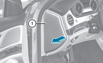
Do not use a pointed object such as a screwdriver to open the cover in the dashboard. You could damage the dashboard or the cover.
- Open the driver’s door.
- To open: pull cover (1) outwards in the direction of the arrow and remove it.
- To close: clip in cover (1) on the front of the dashboard.
- Fold cover (1) inwards until it engages.
Advertisements
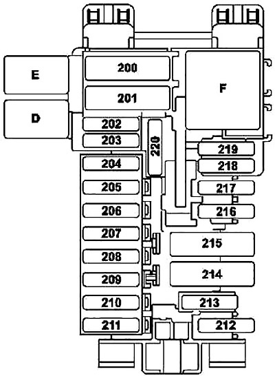
| № | Fused function: | A |
|---|---|---|
| 200 | Front SAM control unit | 40 |
| 201 | Front SAM control unit | 40 |
| 202 | Alarm siren | 5 |
| 203 | W222: Driver seat heater control unit | 30 |
| 204 | Diagnostic connector | 5 |
| 205 | Electronic ignition lock control unit | 7.5 |
| 206 | Analog clock | 5 |
| 207 | Climate control control unit | 20 |
| 208 | Instrument cluster | 7.5 |
| 209 | Front climate control operating unit | 5 |
| 210 | Steering column tube module control unit | 10 |
| 211 | Spare | - |
| 212 | Spare | - |
| 213 | Electronic Stability Program control unit | 25 |
| 214 | Spare | - |
| 215 | Spare | - |
| 216 | Spare | - |
| 217 | Japanese version: Dedicated Short-Range Communications control unit | 5 |
| 218 | Supplemental restraint system control unit | 5 |
| 219 | Weight sensing system (WSS) control unit | 5 |
| Front passenger seat occupied recognition and ACSR | ||
| 220 | MAGIC VISION CONTROL relay | 15 |
| D | MAGIC VISION CONTROL relay | |
| E | Backup relay | |
| F | Relay, circuit 15R | |
Fuse box in the front-passenger footwell
- Open the front-passenger door.
- Fold cover (1) down and remove it.
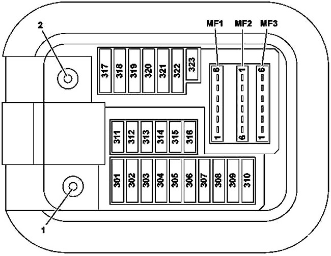
- Circuit 30 “E1” connection
- Circuit 30g “E2” connection
| № | Fused function | A |
|---|---|---|
| 301 | Mirror taximeter | 5 |
| 302 | Right front door control unit | 30 |
| 303 | W222: Left rear door control unit | 30 |
| C217, A217: Rear control unit | ||
| 304 | W222: Right rear door control unit | 30 |
| C217, A217: Rear control unit | ||
| 305 | Driver seat control unit | 30 |
| 306 | Front passenger seat control unit | 30 |
| 307 | W222: Intelligent servo module for DIRECT SELECT | 20 |
| C217, A217: Driver seat heater control unit | 30 | |
| 308 | Front passenger seat heater control unit | 30 |
| 309 | Emergency call system control unit | 5 |
| Telematics services communications module | ||
| HERMES control unit | ||
| 310 | Stationary heater control unit | 25 |
| 311 | Rear blower motor | 10 |
| 312 | Overhead control panel control unit | 10 |
| 313 | Hybrid and Hybrid Plus: Power electronics control unit | 10 |
| 314 | A217: Antitheft alarm system (designation in coordination) | 7.5 |
| 315 | Powertrain control unit | 10 |
| Valid for gasoline engine: ME-SFI control unit | ||
| Valid for engine 642, 651: CDI control unit | ||
| 316 | Spare | - |
| 317 | W222: Panoramic sliding sunroof control module | 30 |
| C217, A217: MAGIC SKY CONTROL control unit | ||
| 318 | Audio/COMAND display | 15 |
| 319 | Panoramic sliding sunroof control module | 30 |
| C217, A217: Panoramic roof roller sun blind control module | ||
| 320 | Active Body Control control unit | 15 |
| AIRmatic control unit (Valid except Active Body Control) | ||
| 321 | C217, A217: Intelligent servo module for DIRECT SELECT | 20 |
| 322 | COMAND controller unit | 15 |
| 323 | Supplemental Restraint System control unit | 7.5 |
| MF1/1 | Japan version: Dedicated Short-Range Communications control unit | 7.5 |
| MF1/2 | Mono multifunction camera | 7.5 |
| Stereo multifunction camera | ||
| MF1/3 | Rain/light sensor with additional functions | 7.5 |
| Overhead control panel control unit | ||
| MF1/4 | Driver seat control unit | 7.5 |
| MF1/5 | Front passenger seat control unit | 7.5 |
| MF1/6 | Steering column tube module control unit | 7.5 |
| MF2/1 | Perfume atomizer generator | 5 |
| MF2/2 | Audio/COMAND control panel | 5 |
| Touchpad | ||
| MF2/3 | Electronic Stability Program control unit | 5 |
| MF2/4 | Heads-up display | 5 |
| MF2/5 | Hybrid and Hybrid Plus: Electrical refrigerant compressor | 5 |
| MF2/6 | Spare | - |
| MF3/1 | Front SAM control unit | 5 |
| MF3/2 | Radar sensors control unit | 5 |
| MF3/3 | COMAND fan motor | 5 |
| MF3/4 | Driver side instrument panel button group | 5 |
| Center instrument panel button group | ||
| MF3/5 | Rear air conditioning operating unit | 5 |
| MF3/6 | as of 01.06.2016: Antenna changeover switch for telephone and stationary heater | 5 |
Advertisements
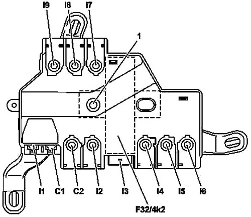
Interior prefuse box
| № | Fused function | A |
|---|---|---|
| I7 | Right A-pillar fuse box | 125 |
| I2 | Left fuse and relay module | 125 |
| C2 | Spare | - |
| I8 | Spare | - |
| I9 | Spare | - |
| I3 | No-load current shutoff relay connection | - |
| C1 | Blower regulator | 40 |
| I1 | Electronic Stability Program control unit | 40 |
| I4 | Spare | - |
| I6 | Rear fuse and relay module | 60 |
| I5 | Right A-pillar fuse box | 60 |
| F32/4k2 | Quiescent current cutout relay | |
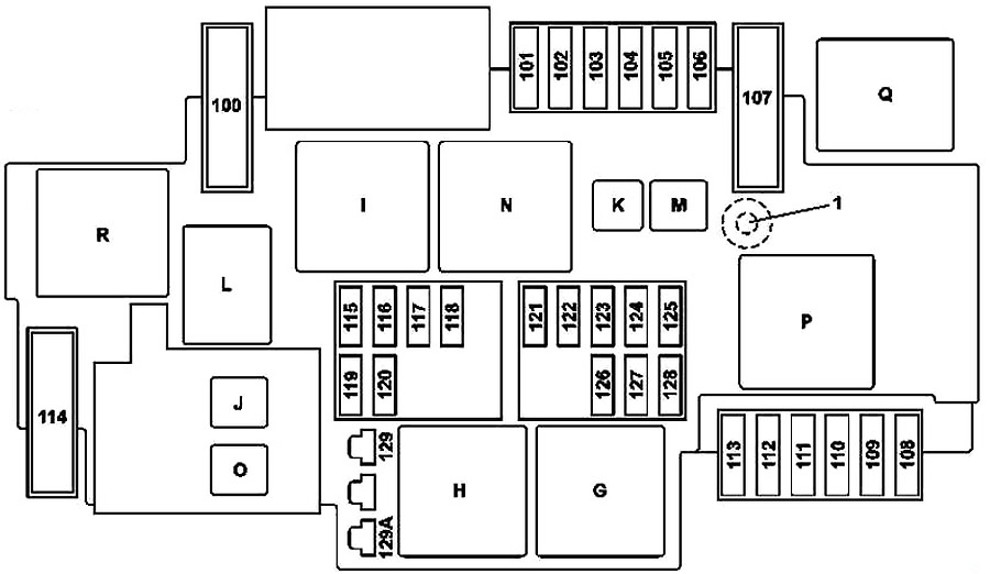
Engine Compartment Fuse Box
It is on the left-hand side of the vehicle, when viewed in the direction of travel.
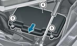
- Open the hood.
- To open: release retaining clamps (1) and remove cover (2).
- Use a dry cloth to remove any moisture from the fuse box.
- Undo screws (3) on the fuse box.
- Remove fuse box cover (4) forwards.
- To close: check whether the seal is lying correctly in cover (4).
- Insert cover (4) at the rear of the fuse box into the retainer.
- Fold-down cover (4) of the fuse box and tighten screws (3).
- Insert cover (2) and secure with retaining clamps (1).
- Close the hood.
Advertisements
| № | Fused function | A |
|---|---|---|
| 100 | Hybrid: Vacuum pump | 40 |
| 101 | Connector sleeve, circuit 87/2 | 15 |
| 102 | Connector sleeve, circuit 87/2 | 20 |
| 103 | Connector sleeve, circuit 87M4 | 15 |
| 104 | Connector sleeve, circuit 87M3 | 15 |
| 105 | Valid for transmission 722.9: Transmission oil auxiliary pump control unit | 15 |
| 106 | Wiper park position heater | 25 |
| 107 | Valid for engine 277, 279: Starter/air pump electrical connection | 60 |
| 108 | Valid for SAE dynamic LED headlamp for right-hand traffic or Dynamic LED headlamp:: | 20 |
| Left front lamp unit | ||
| Right front lamp unit | ||
| Valid without SAE dynamic LED headlamp for right-hand traffic or Dynamic LED headlamp:: | ||
| Right front lamp unit | ||
| 109 | Wiper motor | 30 |
| 110 | Valid for code SAE dynamic LED headlamp for right-hand traffic or Dynamic LED headlamp:: | 20 |
| Left front lamp unit | ||
| Right front lamp unit | ||
| Valid without SAE dynamic LED headlamp for right-hand traffic or Dynamic LED headlamp:: | ||
| Left front lamp unit | ||
| 111 | Starter | 30 |
| 112 | Engine fuse and relay module | 5 |
| 113 | Spare | - |
| 114 | AIRmatic compressor | 40 |
| 115 | Left fanfare horn | 15 |
| Right fanfare horn | ||
| 116 | Hybrid: Vacuum pump relay | 5 |
| 117 | Spare | - |
| 118 | Hybrid: Electronic Stability Program control unit | 5 |
| 119 | Circuit 87/C2 connector sleeve | 15 |
| 120 | Circuit 87/C1 connector sleeve | 7.5 |
| 121 | Electronic Stability Program control unit | 5 |
| 122 | Hybrid: HYBRID relay | 5 |
| 123 | Night View Assist control unit | 5 |
| 124 | Hybrid: Vehicle interior and engine compartment electrical connector | 5 |
| 125 | Front SAM control unit | 5 |
| 126 | Powertrain control uni | 5 |
| Valid for diesel engine: CDI control unit | ||
| Valid for gasoline engine: ME-SFI [ME] control unit | ||
| 127 | Spare | - |
| 128 | Exterior lights switch | 5 |
| 129A | Hybrid: Starter circuit 50 relay | 30 |
| 129B | Valid except Hybrid: Starter circuit 50 relay | 30 |
| G | Engine compartment circuit 15 relay | |
| H | Starter circuit 50 relay | |
| I | Brake vacuum pump relay | |
| J | Hybrid: HYBRID relay | |
| K | Transmission oil pump relay | |
| L | Horn relay | |
| M | Wiper park position heater relay | |
| N | Circuit 87M relay | |
| O | Valid except Hybrid: Starter circuit 15 relay | |
| P | Secondary air injection relay | |
| Q | Hybrid: Vacuum pump relay | |
| R | AIRmatic relay | |
Engine compartment prefuse box
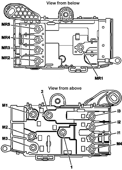
- Connection, circuit 30 “B1”
- Connection, circuit 30 unlatched “B2”
| № | Fused function | A |
|---|---|---|
| M3 | Hybrid: Electrical machine | 500 |
| Valid except Hybrid: Alternator | 500 | |
| M1 | Hybrid: Electrical machine | - |
| Valid except Hybrid: Starter | - | |
| MR5 | Electrical power steering control unit | 100 |
| MR2 | Fan motor | 100 |
| M4 | Hybrid: Fully integrated transmission control controller unit | 100 |
| I1 | Spare | - |
| M2 | Valid for diesel engine: Glow output stage | 150 |
| MR1 | Motor fuse and relay module | 60 |
| MR3 | Spare | - |
| MR4 | Valid for engine 277, 279: Fan motor | 150 |
| I2 | Spare | - |
Advertisements
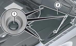
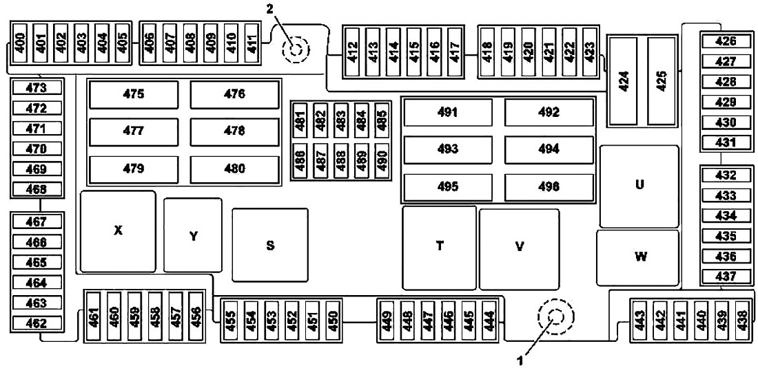
Luggage Compartment Fuse Box
The fuse block is placed on the right-hand side of the trunk, when viewed in the direction of travel.
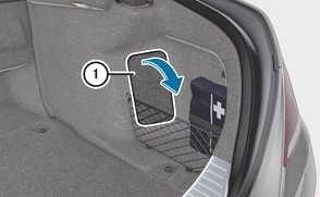
- Open the trunk lid.
- To open: release cover (1) at the top right and left-hand sides with a flat object.
- Open cover (1) downwards in the direction of the arrow.
- Circuit 30 “E1” connection
- Circuit 30g “E2” connection
| № | Fused function | A |
|---|---|---|
| 400 | Parking system control unit (Active Parking Assist or code 360-degree camera) | 10 |
| 401 | Trunk lid control control unit | 5 |
| 402 | Rear entertainment controller unit | 7.5 |
| 403 | Spare | - |
| 404 | Armrest heater control unit | 7.5 |
| 405 | Sound system amplifier control unit | 7.5 |
| Left front door tweeter control unit | ||
| Right front door tweeter control unit | ||
| 406 | Spare | - |
| 407 | Spare | - |
| 408 | Tuner unit | 5 |
| 409 | 360° camera control unit | 5 |
| Reversing camera | ||
| 410 | Camera cover control unit | 5 |
| 411 | Tire pressure monitor control unit | 5 |
| 412 | Rear seat heater control unit | 7.5 |
| 413 | Left rear display | 10 |
| Right rear display | ||
| 414 | Rear cellular telephone system antenna amplifier/compensator | 7.5 |
| Rear mobile phone cradle | ||
| Rear mobile phone contact plate | ||
| Telephone module with Bluetooth (SAP profile) | ||
| 415 | Spare | - |
| 416 | Spare | - |
| 417 | Trailer recognition control unit | 20 |
| 418 | Spare | - |
| 419 | Spare | - |
| 420 | DC/AC converter control unit | 30 |
| 421 | Multicontour seat pneumatic pump | 30 |
| 422 | W222: Right rear door control unit | 30 |
| 423 | Spare | - |
| 424 | Rear SAM control unit | 40 |
| 425 | Spare | - |
| 426 | Bass speaker amplifier | 30 |
| 427 | Armrest heater control unit | 20 |
| 428 | Trailer recognition control unit | 15 |
| 429 | Rear cup holder | 10 |
| 430 | Cigarette lighter with ashtray illumination, rear | 15 |
| Cigarette lighter with rear center console illumination | ||
| Left rear center console socket 12V (ashtray package/smoker package) | ||
| 431 | Rear backrest refrigerator box | 15 |
| 432 | Rear SAM control unit | 10 |
| 433 | AdBlue control unit | 25 |
| 434 | AdBlue control unit | 15 |
| 435 | AdBlue control unit | 20 |
| 436 | Rear cup holder | 20 |
| 437 | Spare | - |
| 438 | C217 with engine 157: Right exhaust flap actuator motor | 7.5 |
| 439 | C217 with engine 157: Left exhaust flap actuator motor | 7.5 |
| 440 | Spare | - |
| 441 | Spare | - |
| 442 | Spare | - |
| 443 | Spare | - |
| 444 | Spare | - |
| 445 | Stationary heater radio remote control receiver | 5 |
| 446 | FM 1, AM, CL [ZV] and KEYLESS-GO antenna amplifier | 5 |
| 447 | Hybrid: Battery management system control unit | 7.5 |
| 448 | Spare | - |
| 449 | Spare | - |
| 450 | Spare | - |
| 451 | Trailer socket | 15 |
| 452 | Left rear bumper radar sensor | 5 |
| Right rear bumper radar sensor | ||
| Center rear bumper radar sensor | ||
| 453 | Left front bumper radar sensor | 5 |
| Right front bumper radar sensor | ||
| COLLISION PREVENTION ASSIST controller unit | ||
| 454 | AdBlue control unit | 5 |
| Fuel system control unit | ||
| 455 | Fully integrated transmission control controller unit | 15 |
| 456 | Spare | - |
| 457 | Valid for lithium-ion battery: Starter battery capacitor | 7.5 |
| 458 | Spare | - |
| 459 | Spare | - |
| 460 | Front cigarette lighter with ashtray illumination | 15 |
| 461 | Right rear center console socket 12V | 15 |
| Socket 12V | ||
| DC/AC converter control unit | ||
| 462 | Luggage compartment socket | 15 |
| 463 | Spare | - |
| 464 | Trailer recognition control unit | 20 |
| 465 | Electric parking brake control unit | 30 |
| 466 | Left front door control unit | 30 |
| 467 | KEYLESS-GO control unit | 10 |
| 468 | Electric parking brake control unit | 30 |
| 469 | Fuel system control unit | 25 |
| 470 | Left rear seat heater control unit | 30 |
| Rear seat heater control unit | ||
| 471 | Right rear seat heater control unit | 30 |
| 472 | C217, A217: Rear control unit | 30 |
| 473 | Trailer recognition control unit | 20 |
| 475 | Sound system amplifier control unit | 40 |
| 476 | Sound system amplifier control unit | 40 |
| 477 | Active belt buckle control unit | 40 |
| C217, A217: Rear control unit | ||
| 478 | Left rear seat control unit | 30 |
| 479 | Active belt buckle control unit | 40 |
| 480 | Right rear seat control unit | 30 |
| 481 | Left front reversible emergency tensioning retractor | 5 |
| 482 | W222: MAGIC SKY CONTROL control unit | 5 |
| C217, A217: MAGIC SKY CONTROL control unit | 7.5 | |
| 483 | Right front reversible emergency tensioning retractor | 5 |
| 484 | Right rear seat control unit | 7.5 |
| Left rear seat control unit | ||
| 485 | Active belt buckle control unit | 5 |
| 486 | Hybrid: | 10 |
| Battery management system control unit | ||
| Power electronics control unit | ||
| 487 | Electric parking brake control unit | 5 |
| 488 | Rear SAM control unit | 5 |
| 489 | Front long-range radar sensor | 5 |
| 490 | Multicontour seat pneumatic pump | 5 |
| 491 | Trunk lid control control unit | 40 |
| 492 | Right front reversible emergency tensioning retractor | 40 |
| 493 | Spare | - |
| 494 | Rear SAM control unit | 40 |
| 495 | Rear window heater | 40 |
| 496 | Left front reversible emergency tensioning retractor | 40 |
| S | Vehicle interior circuit 15 relay | |
| T | Rear window heater relay | |
| U | 2nd seat row cupholder and sockets relay | |
| V | AdBlue relay | |
| W | Circuit 15R relay | |
| X | 1 st seat row/trunk refrigerator box and sockets relay | |
| Y | Spare relay | |
Rear prefuse box
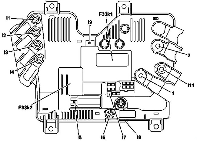
| № | Fused function | A |
|---|---|---|
| I3 | Spare | - |
| I2 | Windshield heater control unit | 125 |
| I7 | Hybrid: High-voltage disconnect device | 7.5 |
| I4 | Rear fuse and relay module | 150 |
| I6 | ECO start/stop function additional battery | 200 |
| I7 | ECO start/stop function additional battery | 10 |
| Front SAM control unit | ||
| Electronic ignition lock control unit | ||
| I1 | Spare | - |
| I11 | Spare | - |
| I7 | Front SAM control unit | 10 |
| I8 | ECO start/stop function additional battery relay connection | - |
| I5 | Hybrid: High-voltage pyrofuse triggered by Supplemental Restraint System control unit | - |
| I9 | Decoupling relay connection | - |
| F33k1 | Decoupling relay | |
| F33k2 | ECO start/stop function additional battery relay | |
Advertisements