
Advertisements
Fuse box diagram (fuse layout), location, and assignment of fuses and relays Mercedes-Benz S-Class (W221) and CL-Class (C216) (250, 280, 300, 320, 350, 400, 420, 450, 500, 550, 600, 63, 65) (2005, 2006, 2007, 2008, 2009, 2010, 2011, 2012, 2013).


Checking and Replacing Fuses
The fuses in your vehicle serve to close down faulty circuits. If a fuse blows, all the components on the circuit and their functions stop operating. If a fuse has blown, the inside element will be melted. Blown fuses must be replaced with fuses of the same rating, which you can recognize by the color and value. The fuse ratings are listed in the fuse allocation chart (is in the vehicle document wallet).
If a newly inserted fuse also blows, have the cause traced and rectified at a qualified specialist workshop, e.g. an authorized Mercedes-Benz Center.
Notice
- Before changing a fuse, secure the vehicle against rolling away and switch off all electrical consumers.
- Always disconnect the battery before servicing high current fuses.
- Always replace faulty fuses with the specified new fuses having the correct amperage. If you manipulate or bridge a faulty fuse or if you replace it with a fuse with a higher amperage, the electric cables could be overloaded. This could result in a fire. There is a risk of an accident and injury.
- Only use fuses that have been approved for Mercedes-Benz vehicles and which have the correct fuse rating for the system concerned. Otherwise, components or systems could be damaged.
Left Instrument Panel Fuse Box
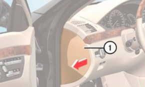
Do not use a pointed object such as a screwdriver to open the cover in the dashboard. You could damage the dashboard or the cover.
- To open: pull cover (1) outwards in the direction of the arrow and remove it.
- To close: clip in cover (1) on the front of the dashboard.
- Fold cover (1) inwards until it engages.
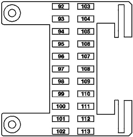
| № | Fused function | A |
|---|---|---|
| 92 | Left front seat control unit | 40 |
| 93 | Restraint systems control unit | 7.5 |
| USA version: Weight Sensing System (WSS) control unit | ||
| 94 | from 2009: Multifunction camera | 5 |
| 95 | - | - |
| 96 | Tire pressure monitor [RDK] control unit | 5 |
| 97 | W221: Audio/video controller control unit (rear entertainment system) | 7.5 |
| 98 | Rear entertainment system: DVD player (from 2009) | 7.5 |
| 99 | from 2009: | 7.5 |
| COMAND display | ||
| SPLITVIEW display | ||
| 100 | from 2009: Media interface control unit | 5 |
| 101 | Rear entertainment system: | 10 |
| Left rear display | ||
| Right rear display | ||
| 102 | Right front seat control unit | 40 |
| 103 | ESP control unit | 7.5 |
| 104 | Audio tuner control unit | 40 |
| 105 | - | - |
| 106 | Japanese version: Electronic toll collection (ETC) control unit | 1 |
| Valid for South Korea as of 1.9.10: TV/tuner connector | ||
| Valid for navigation; from 2009: Navigation processor | ||
| 107 | SDAR control unit (SIRIUS satellite radio) (W221 from 2009) | 5 |
| Digital radio: Digital Audio Broadcasting control unit | ||
| HD radio: High definition tuner control unit | ||
| 108 | W221: Rear air conditioning control unit | 5 |
| 109 | W221: Rear blower intermediate connector | 15 |
| 110 | W221: | 7.5 |
| Left rear multicontour backrest control unit | ||
| Right rear multicontour backrest control unit | ||
| 111 | Rear multicontour seat or rear entertainment system (model 221): RCP [HBF] control unit | 5 |
| 112 | W221; up 2008: | 5 |
| Left front door control unit | ||
| Right front door control unit | ||
| S 400 Hybrid: Front SAM control unit with fuse and relay module | ||
| 113 | S 400 Hybrid: DC/DC converter control unit | 5 |
Advertisements
Right Instrument Panel Fuse Box
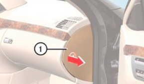
Do not use a pointed object such as a screwdriver to open the cover in the dashboard. You could damage the dashboard or the cover.
- To open: pull cover (1) outwards in the direction of the arrow and remove it.
- To close: clip in cover (1) on the front of the dashboard.
- Fold cover (1) inwards until it engages.
| № | Fused function | A |
|---|---|---|
| 70 | C216: Right door control unit | 40 |
| W221: Right front door control unit | ||
| 71 | Keyless Go control unit | 15 |
| 72 | S 400 Hybrid: Pyrotechnical separator | 7.5 |
| 73 | Japanese version: COMAND controller unit | 5 |
| TELE AID emergency call system (from 2009): Emergency call system control unit | ||
| 74 | TLC [HDS] control unit (Remote trunk closing) | 30 |
| 75 | S 400 Hybrid: | 10 |
| Battery management system control unit | ||
| Power electronics control unit | ||
| 76 | S 400 Hybrid: Vacuum pump relay (+) | 15 |
| Valid for model 221 with engine 642.8: AdBlue relay supply | - | |
| 77 | Advanced sound system: Sound amplifier (from 2009) | 50 |
| 78 | S 65 AMG with engine 275: | 25 |
| Additional fan relay (from 2009) | ||
| Valid for model 221 with engine 642.8: | ||
| AdBlue relay supply (from 2009) | ||
| S 400 Hybrid, CL 63 AMG with engine 157, 278: | 15 | |
| Charge air cooler circulation pump (from 2009) | ||
| 79 | Alarm signal horn with additional battery | 7.5 |
| 80 | C216: Left door control unit | 40 |
| W221: Left front door control unit | ||
| 81 | C216: Rear control unit | 30 |
| W221: Left rear door control unit | 40 | |
| 82 | C216: Rear control unit | 30 |
| W221: Left rear door control unit | 40 | |
| 83 | Intelligent servo module for DIRECT SELECT | 30 |
| 84 | Advanced sound system: Digital sound processor (from 2009) | 20 |
| 85 | Valid for AMG: Illuminated door sill moldings (from 2009) | 10 |
| 86 | - | - |
| 87 | - | - |
| 88 | - | - |
| 89 | - | - |
| 90 | Stationary heater: | 20 |
| STH heater unit (model 216) | ||
| STH or HB heater unit (model 221) | ||
| 91 | Stationary heater: | 5 |
| STH radio remote control receiver | ||
| S 400 Hybrid: | ||
| Front SAM control unit with fuse and relay module |
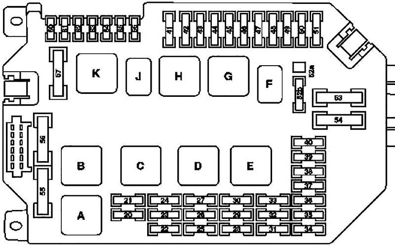
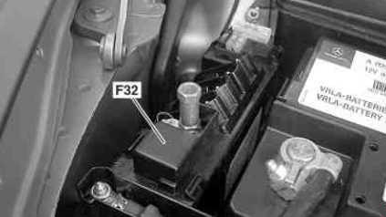
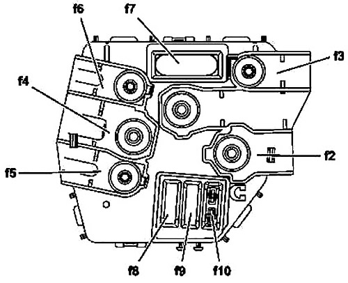
Engine Compartment Fuse Box
It is on the left-hand side of the vehicle, when viewed in the direction of travel.
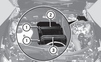
- Remove any existing moisture from the fuse box using a dry cloth.
- AMG vehicles: remove the control unit above the fuse box.
- To open: undo screws (1) with an Allen key.
- Remove bracket (3).
- Remove cover (2).
- To close: check whether the rubber seal is lying correctly in cover (2).
- Put cover (2) back in position.
- Replace bracket (3).
- Tighten screws (1) using an Allen key.
Advertisements
| № | Fused function | A |
|---|---|---|
| 20 | Valid for engine 629, 642, 651: | 10 |
| CDI control unit | ||
| Valid for engines 156, 157, 272, 273, 275, 276, 278: | ||
| ME-SFI [ME] control unit | ||
| 21 | Valid for engines 156, 157, 272, 273, 275, 276, 278: | 20 |
| Terminal 87 M1 i connector sleeve | ||
| Valid for model 221 with engine 629 and engine 642: | ||
| CDI control unit | ||
| Fuel pump relay | ||
| Valid for model 221 with engine 651: | ||
| Quantity control valve | ||
| 22 | Valid for engines 156, 157, 272, 273, 276, 278: | 15 |
| Terminal 87 connector sleeve | ||
| 23 | up 2008: | 20 |
| Terminal 87 connector sleeve | ||
| Valid for engine 275 (model 216): | ||
| Terminal 87 M1 i connector sleeve | ||
| Valid for engine 273 (model 216): | ||
| Terminal 87 M2e connector sleeve | ||
| Valid for engine 272, 273 (model 221): | ||
| Terminal 87M2i connector sleeve | ||
| Valid for engine 642: | ||
| Terminal 87 connector sleeve | ||
| from 2009: | ||
| Valid for engine 156, 157, 272, 273, 275, 276, 278: | ||
| Terminal 87 connector sleeve | ||
| Valid for model 221 with engine 629 and engine 642: | ||
| Terminal 87 connector sleeve | ||
| Valid for engine 156, 157, 272, 273, 276, 278: | ||
| Terminal 87M2e connector sleeve | ||
| Valid for engine 275: | ||
| Terminal 87 M2i connector sleeve | ||
| Valid for model 221 with engine 629 and engine 642: | ||
| Terminal 87 connector sleeve | ||
| Valid for model 221 with engine 651: | ||
| Rear SAM control unit with fuse and relay module | ||
| 24 | Valid for engines 157, 272, 273, 276, 278: | 25 |
| Terminal 87M1e connector sleeve | ||
| Valid for engine 642: | ||
| CDI control unit | ||
| 25 | Instrument cluster | 7.5 |
| 26 | Left front lamp unit | 10 |
| 27 | Right front lamp unit | 10 |
| 28 | Valid for engine 275: | 7.5 |
| EGS control unit | ||
| Valid without engine 275: | ||
| Fully integrated transmission control (VGS) control unit | ||
| 29 | Rear SAM control unit with fuse and relay module | 5 |
| 30 | Valid for engine 629, 642, 651: | 7.5 |
| CDI control unit | ||
| Valid for engines 156, 157, 272, 273, 275, 276, 278: | ||
| ME-SFI [ME] control unit | ||
| Fuel pump control unit | ||
| 31 | S 400 Hybrid: Electric refrigerant compressor | 5 |
| 32 | Valid for model with ECO start/stop function: | 15 |
| Transmission oil auxiliary pump control unit | ||
| S 400 Hybrid: | ||
| Transmission oil auxiliary pump control unit | ||
| 33 | Valid as of 1.9.10 without model S 400 Hybrid: | 5 |
| ESP control unit | ||
| S 400 Hybrid: | ||
| Battery management system control unit | ||
| DC/DC converter control unit | ||
| Power electronics control unit | ||
| 34 | S 400 Hybrid: Regenerative braking system control unit | 5 |
| 35 | Electric parking brake controller unit | 5 |
| 36 | Data link connector (Pin 16) | 10 |
| 37 | For EIS control unit | 7.5 |
| 38 | Central gateway control unit | 7.5 |
| 39 | Instrument cluster | 7.5 |
| 40 | Upper control panel control unit | 7.5 |
| 41 | Slave wiper motor | 30 |
| 42 | Master wiper motor | 30 |
| 43 | Front cigar lighter with ashtray illumination | 15 |
| 44 | - | - |
| 45 | S 400 Hybrid: Power electronics circulation pump 1 | 5 |
| 46 | W221 with Active Body Control (ABC), model 216: ABC control unit | 15 |
| W221 without Active Body Contro (ABC): AIRmatic with ADS control unit | ||
| 47 | Front SAM control unit with fuse and relay module | 15 |
| Steering column up/down motor | ||
| 48 | up 2008: Front SAM control unit with fuse and relay module | 15 |
| from 2009: Steering column in/out motor | ||
| 49 | Steering column module | 10 |
| 50 | AAC [KLA] control unit | 15 |
| 51 | up 2008: COMAND display | 7.5 |
| from 2009: | 5 | |
| COMAND display | ||
| SPLITVIEW display | ||
| 52 A | W221: | 15 |
| Left fanfare horn | ||
| Right fanfare horn | ||
| 52 B | W221, C216: | 15 |
| Left fanfare horn | ||
| Right fanfare horn | ||
| 53 | - | - |
| 54 | AC air recirculation unit | 40 |
| 55 | Valid for gasoline engine: Electric air pump | 60 |
| 56 | W221 without Active Body Contro (ABC): AIRmatic compressor unit | 40 |
| 57 | up 2008: Wiper park position heater | 40 |
| from 2009: Wiper park position heater | 30 | |
| 60 | from 2009: Electrohydraulic power steering | 5 |
| 61 | C216; W221 - from 2009: Restraint systems control unit | 7.5 |
| W221; up 2008: Restraint systems control unit | 10 | |
| 62 | Night View Assist control unit | 5 |
| 63 | Valid for model 221 with engine 629 and engine 642 as of 1.9.08: Fuel filter condensation sensor with heating element | 15 |
| 64 | W221 as of 1.9.06: | 7.5 |
| Driver NECK-PRO head restraint solenoid | ||
| Front passenger NECK-PRO head restraint solenoid | ||
| W221 as of '09: | 10 | |
| Driver NECK-PRO head restraint solenoid | ||
| Front passenger NECK-PRO head restraint solenoid | ||
| 65 | Valid as of 1.6.09: 12 Volt connector in glove box | 15 |
| 66 | DTR controller unit (Distronic or Distronic Plus) | 7.5 |
| A | Air pump relay | |
| B | Air suspension compressor relay | |
| C | Terminal 87 relay, engine | |
| D | Terminal 15 relay | |
| E | Terminal 87 relay, chassis | |
| F | Fanfare horn relay | |
| G | Terminal 15R relay | |
| H | Circuit 50 relay, starter | |
| J | Circuit 15 relay, starter | |
| K | Wiper park heater relay | |
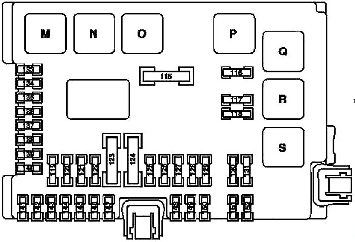
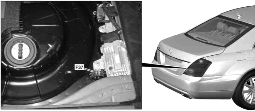
Rear Fuse Box
The fuse box is behind the armrest in the rear.
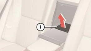
To open: Swing down center armrest. Open cover behind the center armrest. Pull cover 1 forward in direction of the arrow.
To close: Press cover 1 backward and engage.
Advertisements
| № | Fused function | A |
|---|---|---|
| 115 | Heated rear window | 50 |
| 116 | Valid for engine 157, 275, 278: Charge air cooler circulation pump | 10 |
| Valid for engine 156: Engine coolant circulation pump | ||
| S 400 Hybrid: Power electronics circulation pump 2 | ||
| 117 | Rear cigar lighter | 15 |
| 118 | Valid for engine 272, 273, 642: Fuel pump (up 2008) | 30 |
| Valid for model 221 with engine 629, 642: Fuel pump (from 2009) | ||
| S 400 Hybrid: Power electronics circulation pump 1 | 15 | |
| Valid for model 642.8 and engine 651 as of 1.6.11: Refrigerant compressor with magnetic | ||
| 119 | Front central operating unit | 7.5 |
| 120 | - | - |
| 121 | Audio tuner control unit | 10 |
| 122 | COMAND controller unit | 7.5 |
| 123 | W221: Right front reversible emergency tensioning retractor | 40 |
| 124 | W221: Left front reversible emergency tensioning retractor | 40 |
| 125 | up 31.5.09: Voice control system (VCS) control unit | 5 |
| 126 | Overhead control panel control unit | 25 |
| 127 | Lumbar pump (from 2009) | 30 |
| Multicontour seat pneumatic pump (Left/right front multicontour seats) | ||
| Pneumatic pump for dynamic seat control (Left and right dynamic multicontour seat) | ||
| 128 | Valid for engine 275 (up 2008): Fuel pump control unit | 25 |
| Valid for engine 156, 157, 272, 273, 275, 276, 278, 642 (from 2009): Fuel pump control unit | ||
| 129 | up 2008: Overhead control panel control unit (Power glass tilting/sliding roof) | 25 |
| from 2009: UPCI (Universal Portable Cell Phone Interface) control unit | ||
| 130 | Electric parking brake controller unit | 30 |
| 131 | Rear window antenna amplifier module | 7.5 |
| 133 | Trailer recognition control unit | 15 |
| Reversing camera (as of 1.9.10) | ||
| 134 | Luggage compartment socket | 15 |
| 135 | Park Assist; up 2008: | 7.5 |
| Radar sensors control unit (SGR) | ||
| Front short range radar sensor unit | ||
| Rear short range radar sensor unit | ||
| DISTRONIC PLUS up to 31.8.10 or Blind Spot Assist or Adaptive cruise control Plus Light: Radar sensors control unit (SGR) (from 2009) | ||
| PARKTRONIC or Exclusive parking assist: PTS control unit | ||
| 136 | Valid for model 221 with engine 642.8: AdBlue control unit | 7.5 |
| 137 | Reversing camera (as of 1.9.10) | 7.5 |
| 138 | Navigation processor (from 2009) (up to 31.8.10) | 5 |
| Emergency call system control unit (from 2009) | ||
| Japanese version: TV/tuner connector (from 2009) | ||
| 139 | Rear backrest refrigerator box | 15 |
| 140 | Rear cigar lighter with ashtray illumination connector | 15 |
| 115 V socket (from 2009) | ||
| 141 | Reversing camera control unit | 5 |
| 142 | Parktronic system (PTS) control unit | 7.5 |
| Distronic Plus: Radar sensors control unit (SGR) | ||
| Valid as of 1.9.10 for DISTRONIC PLUS and Active Blind Spot Assist or Active Lane Keeping Assist: | ||
| Video and radar sensor system control unit | ||
| 143 | Rear seats control unit | 25 |
| 144 | Rear seats control unit | 25 |
| 145 | Trailer recognition control unit (up 2008) | 20 |
| Trailer hitch socket (13-pin) (from 2009) | ||
| 146 | Trailer recognition control unit | 25 |
| 147 | up 2008: TLC [HDS] control unit (Remote trunk closing) | 30 |
| 148 | up 2008: Universal Portable CTEL Interface (UPCI [UHI]) control unit | 7.5 |
| from 2009: Panoramic sliding sunroof circuit 30 connector sleeve | 25 | |
| 149 | up 2008: Voice control system (VCS [SBS]) control unit | 5 |
| from 2009: Panoramic sliding sunroof control module | 25 | |
| 150 | TV combination tuner (analog/digital) | 7.5 |
| Japanese version: TV/tuner connector (from 2009) | ||
| 151 | W221; up 2008: Electric parking brake controller unit | 25 |
| W221; from 2009: Trailer recognition control unit | 20 | |
| 152 | W221: Rear window antenna amplifier module | 7.5 |
| 115 V socket: DC/AC converter control unit | 25 | |
| M | Terminal 15 relay | |
| N | Terminal 15R relay | |
| O | Power outlet relay | |
| P | Heated rear window relay | |
| Q | Valid for engine 156, 157, 275, 278, 629: Circulation pump relay | |
| S 400 Hybrid: Valid for model 221.095/195: Power electronics circulation pump relay 2 | ||
| R | Cigar lighter relay | |
| S | Fuel pump relay | |
| Valid for engine 642.8 and engine 651 as of 1.6.11: Connected through the fuel pump: Refrigerant compressor magnetic clutch | ||
| S 400 Hybrid: Power electronics circulation pump relay 1 | ||
Interior prefuse box
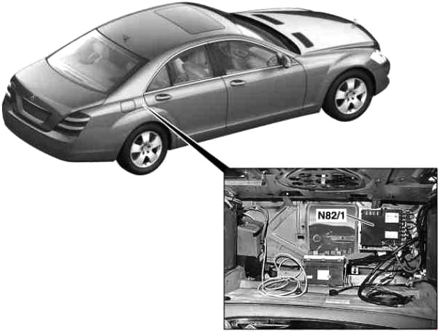
up 2008
| № | Fused function | A |
|---|---|---|
| 1 | Starter | 400 |
| 2 | Not valid for engine 642: | 150 |
| Alternator | 200 | |
| Valid for engine 642: | ||
| Alternator | ||
| 3 | - | 150 |
| 4 | AAC with integrated control additional fan motor | 150 |
| 5 | Valid for engine 642: PTC heater booster | 200 |
| 6 | Front SAM control unit with fuse and relay module | 200 |
| 7 | ESP control unit | 40 |
| 8 | ESP control unit | 25 |
| 9 | Front SAM control unit with fuse and relay module | 20 |
| 10 | Vehicle power supply control unit | 7.5 |
from 2009
| № | Fused function | A |
|---|---|---|
| 3 | Rear SAM control unit with fuse and relay module | 150 |
| 4 | ECO start/stop function: | 150 |
| ECO start/stop function relay | ||
| S 400 Hybrid: | ||
| DC/DC converter control unit | ||
| Heated windshield: | ||
| Heated windshield control unit | ||
| 5 | Valid for model 221 (Electrical preinstallation for rental vehicle):Special vehicle multifunction control unit (SVMCU [MSS]) | 125 |
| S 400 Hybrid: Vacuum pump | 40 | |
| 6 | Right dashboard fuse box | 80 |
| 7 | Valid for model 221 with engine 629, 642, 651: | 150 |
| PTC heater booster | ||
| Valid for model 221 (Electrical preinstallation for rental vehicle): | ||
| Special vehicle multifunction control unit (SVMCU [MSS]) | ||
| 8 | Front SAM control unit with fuse and relay module | 80 |
| 9 | Left dashboard fuse box | 80 |
| 10 | Rear SAM control unit with fuse and relay module | 150 |
Advertisements
Engine compartment prefuse box
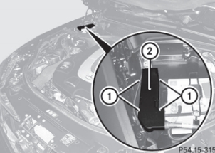
- Remove any existing moisture from the fuse box using a dry cloth.
- To open: open clamps (2).
- Remove cover (2) upwards.
- To close: check whether the rubber seal is lying correctly in cover (2).
- Put cover (2) back in position.
- Fold-down cover (1) and close clamps (2).
up 2008
| № | Fused function | A |
|---|---|---|
| 1 | Front prefuse box | |
| (via on-board electrical network line pyrofuse | ||
| 2 | Heated windshield control unit | 125 |
| 3 | Right instrument panel fuse box | 80 |
| 4 | Rear SAM control unit with fuse and relay module | 200 |
| 5 | Special vehicle multifunction control unit (SVMCU [MSS]) | 100 |
| 6 | Rear SAM control unit with fuse and relay module | 150 |
| 7 | Front SAM control unit with fuse and relay module | 100 |
| 8 | Left instrument panel fuse box | 80 |
| 9 | Front SAM control unit with fuse and relay module | 5 |
| 10 | C216: Emergency call system control unit | 5 |
from 2009
| № | Fused function | A |
|---|---|---|
| 2 | Alternator | 400 |
| 3 | Electrohydraulic power steering | 150 |
| Valid for model 221 with engine 629, 642: | ||
| Glow time output stage | ||
| 4 | Interior prefuse box ( unfused) | - |
| 5 | AAC with integrated control additional fan motor | 100 |
| 6 | Front SAM control unit with fuse and relay module | 150 |
| 7 | ESP control unit | 40 |
| S 400 Hybrid: Regenerative braking system control unit | ||
| 8 | ESP control unit | 25 |
| S 400 Hybrid: Regenerative braking system control unit | ||
| 9 | Front SAM control unit with fuse and relay module | 25 |
| 10 | Spare | - |
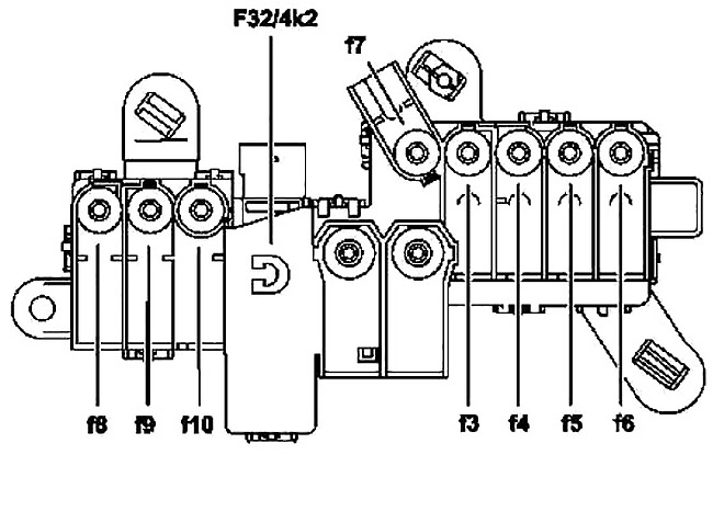
AdBlue fuse block
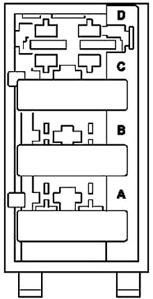
| № | Fused function | A |
|---|---|---|
| A | AdBlue control unit | 7.5 |
| B | Heater circuit 1 | 20 |
| C | Heater circuit 2 | 20 |
| D | Spare | - |
Advertisements