
Advertisements
Fuse box diagram (fuse layout), location, and assignment of fuses and relays Mercedes-Benz R-Class (W251) (R280, R300, R320, R350, R400, R500, R63 AMG) (2006, 2007, 2008, 2009, 2010, 2011, 2012).

Checking and Replacing Fuses
The fuses in your vehicle serve to close down faulty circuits. If a fuse blows, all the components on the circuit and their functions stop operating. If a fuse has blown, the inside element will be melted. Blown fuses must be replaced with fuses of the same rating, which you can recognize by the color and value. The fuse ratings are listed in the fuse allocation chart (located in the vehicle tool kit in the stowage compartment under the trunk floor).
If a newly inserted fuse also blows, have the cause traced and rectified at a qualified specialist workshop, e.g. an authorized Mercedes-Benz Center.
Notice
- Before changing a fuse, secure the vehicle against rolling away and switch off all electrical consumers.
- Always disconnect the battery before servicing high current fuses.
- Always replace faulty fuses with the specified new fuses having the correct amperage. If you manipulate or bridge a faulty fuse or if you replace it with a fuse with a higher amperage, the electric cables could be overloaded. This could result in a fire. There is a risk of an accident and injury.
- Only use fuses that have been approved for Mercedes-Benz vehicles and which have the correct fuse rating for the system concerned. Otherwise, components or systems could be damaged.
Location
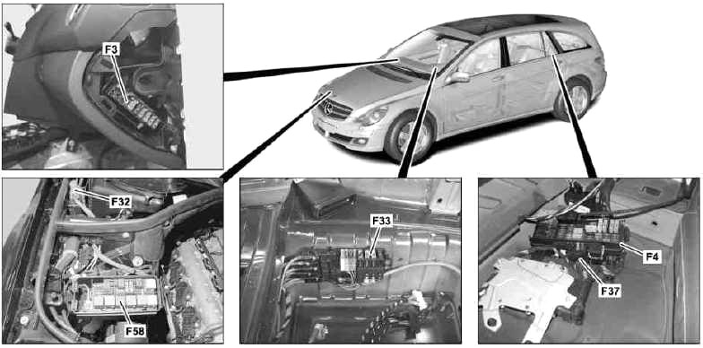
- F3 – Cockpit fuse box
- F4 – Load compartment fuse and relay
- F32 – Front prefuse
- F33 – Battery compartment prefuse box box
- F58 – Engine compartment fuse and relay
Passenger Compartment Fuse Box
The fuse panel is located on the front passenger side of the dashboard.
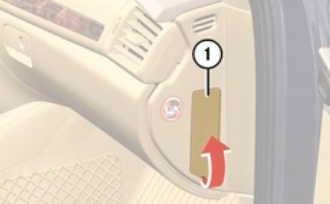
To open:
- Open the front passenger door.
- Pull cover (1) in the direction of the arrow.
To close:
- Clip upper end of cover (1) into the opening.
- Push on the lower end of cover (1) until it engages.
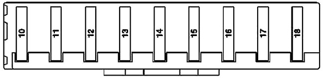
| № | Fused function | A |
|---|---|---|
| 10 | Booster blower electronic blower controller | 10 |
| 11 | Instrument cluster | 5 |
| 12 | Automatic air conditioning [KLA] control and operating unit | 15 |
| Comfort automatic air conditioning [KLA] control and operating unit | ||
| 13 | Upper control panel control unit | 5 |
| Steering column module | ||
| 14 | CD changer (up to 2008) | 7.5 |
| EZS control unit | ||
| 15 | Electronic compass | 5 |
| Media interface control unit (as of 2009) | ||
| 16 | - | - |
| 17 | - | - |
| 18 | - | - |
Advertisements
Battery Compartment Prefuse Box
It is located near the battery under the front passenger’s seat.
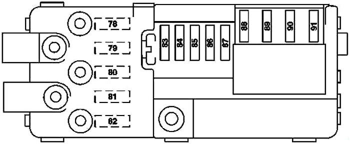
| № | Fused function | A |
|---|---|---|
| 78 | Diesel engine: Heater booster control unit | 150 |
| 79 | Rear SAM control unit | 60 |
| 80 | Rear SAM control unit | 60 |
| 81 | as of 2009: | 40 |
| Valid for engine 642.870: AdBlue® supply relay | ||
| Valid with engine 276: Engine compartment fuse and relay box | ||
| 82 | up to 2008: Load compartment fuse and relay box | 150 |
| as of 2009: Load compartment fuse and relay box | 100 | |
| 83 | USA version: WSS (Weight Sensing System) control unit | 5 |
| 84 | Restraint systems control unit | 10 |
| 85 | as of 2009: DC/AC converter control unit (115 V socket) | 25 |
| 86 | Cockpit fuse box | 30 |
| 87 | - | 30 |
| 88 | up to 2008: Front SAM control unit | 70 |
| as of 2009: Front SAM control unit | 40 | |
| 89 | Front SAM control unit | 70 |
| 90 | Front SAM control unit | 70 |
| 91 | Blower regulator | 40 |
Engine Compartment Fuse Box
It is on the right-hand side of the vehicle, when viewed in the direction of travel.
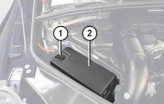
To open:
- Open the hood.
- With a dry cloth, remove any moisture from the fuse box (1).
- Pull clamp (1) in direction of arrow.
- Lift fuse box cover (2) up.
To close:
- Make sure the sealing rubber is positioned properly.
- Press fuse box cover (2) down and secure with clamp (1).
- Close the hood after checking or replacing fuses.
Advertisements
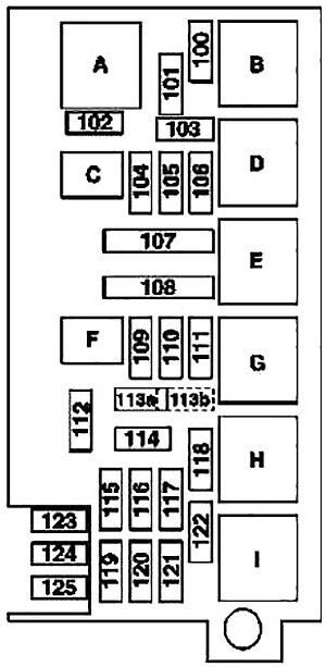
| № | Fused function | A |
|---|---|---|
| 100 | Wiper motor | 30 |
| 101 | up to 2008: | 15 |
| AAC with integrated control additional fan motor | ||
| Valid for engines 113, 272: Purge control valve | ||
| Valid for engine 272: | ||
| Radio interference suppression capacitor 1 | ||
| Radio interference suppression capacitor 2 | ||
| Cylinder 1 ignition coil | ||
| Cylinder 2 ignition coil | ||
| Cylinder 3 ignition coil | ||
| Cylinder 4 ignition coil | ||
| Cylinder 5 ignition coil | ||
| Cylinder 6 ignition coil | ||
| Valid for engine 642: | ||
| O2 sensor upstream of CAT | ||
| CDI control unit | ||
| as of 2009: | ||
| Engine and air conditioning electric suction fan with integrated control | ||
| Valid for engine 272, 273: | ||
| Purging switchover | ||
| Circuit 87 M1e connector sleeve | ||
| Valid with engine 642: | ||
| CDI control unit | ||
| O2 sensor upstream of CAT | ||
| Valid for engine 642.870/872: | ||
| O2 sensor upstream of CAT | ||
| 102 | up to 2008: | 15 |
| Valid for engine 642: | ||
| Recirculation pump for transmission oil cooler | ||
| Valid for engine 156: | ||
| Engine coolant circulation pump | ||
| as of 2009: | ||
| Valid for engine 642, engine 642.870 up to 31.7.10: | ||
| Transmission cooler circulation pump | ||
| Valid with engine 276: | ||
| Charge air cooler circulation pump | ||
| 103 | up to 2008: | 25 |
| Valid for engine 113: | ||
| ME-SFI [ME] control unit | ||
| Cylinder 1 fuel injection valve | ||
| Cylinder 2 fuel injection valve | ||
| Cylinder 3 fuel injection valve | ||
| Cylinder 4 fuel injection valve | ||
| Cylinder 5 fuel injection valve | ||
| Cylinder 6 fuel injection valve | ||
| Cylinder 7 fuel injection valve | ||
| Cylinder 8 fuel injection valve | ||
| Valid for engine 642: | ||
| CDI control unit | ||
| as of 2009: | ||
| Valid for engine 642.950, 642.870/872: CDI control unit | ||
| Valid for engine 272: ME-SFI [ME] control unit | ||
| Valid with engine 276: | ||
| ME-SFI [ME] control unit | ||
| Engine/engine compartment connector | ||
| 104 | up to 2008: | 15 |
| Valid for engine 113: | ||
| Left O2 sensor upstream TWC [KAT] | ||
| Right oxygen O2 sensor upstream of catalytic converter | ||
| Left O2 sensor downstream TWC [KAT] | ||
| Right O2 sensor downstream TWC [KAT] | ||
| Variable intake manifold switchover valve | ||
| EGR vacuum transducer | ||
| Air pump change-over valve | ||
| Valid for engine 272: | ||
| Heating system shutoff valve | ||
| Intake manifold tumble flap switchover valve | ||
| Air pump change-over valve | ||
| Three-disk thermostat valve | ||
| Pressure regulating on the valve power steering unit pump | ||
| Valid for engine 642: | ||
| Left hot film mass air flow sensor | ||
| Right hot film mass air flow sensor | ||
| Intake port shutoff motor | ||
| Glow time output stage | ||
| Vent line heater element | ||
| Power steering pump pressure regulator valve | ||
| Left exhaust gas recirculation positioner | ||
| Boost pressure positioner | ||
| as of 2009: | ||
| Valid for engine 272, 273: Connector sleeve, circuit 87 M2e | ||
| Valid for engine 642.950: Circuit 87 connector sleeve | ||
| Valid for engine 642.870/872: Circuit 87D2 connector sleeve | ||
| 105 | up to 2008: | 15 |
| Valid for engine 113: | ||
| ME control unit | ||
| Radio interference suppression capacitor 1 | ||
| Radio interference suppression capacitor 2 | ||
| Cylinder 1 ignition coil | ||
| Cylinder 2 ignition coil | ||
| Cylinder 3 ignition coil | ||
| Cylinder 4 ignition coil | ||
| Cylinder 5 ignition coil | ||
| Cylinder 6 ignition coil | ||
| Cylinder 7 ignition coil | ||
| Cylinder 8 ignition coil | ||
| Valid for engine 272: | ||
| ME control unit | ||
| Hot film mass air flow sensor | ||
| Hall sensor for left inlet camshaft | ||
| Right intake camshaft Hall sensor | ||
| Left exhaust camshaft Hall sensor | ||
| Right exhaust camshaft Hall sensor | ||
| Left intake camshaft solenoid | ||
| Right camshaft intake solenoid | ||
| Left exhaust camshaft solenoid | ||
| Right exhaust camshaft solenoid | ||
| Cylinder 1 fuel injection valve | ||
| Cylinder 2 fuel injection valve | ||
| Cylinder 3 fuel injection valve | ||
| Cylinder 4 fuel injection valve | ||
| Cylinder 5 fuel injection valve | ||
| Cylinder 6 fuel injection valve | ||
| Valid for engine 642: CDI control unit | ||
| as of 2009: | ||
| Valid for engine 272, 273: | ||
| ME-SFI [ME] control unit | ||
| Circuit 87 M1i connector sleeve | ||
| Valid with engine 276: Engine/engine compartment connector | ||
| Valid for engine 642.950: | ||
| CDI 1.0 PK control unit | ||
| Engine compartment/interior compartment connector | ||
| Valid for engine 642.870/872: | ||
| CDI control unit | ||
| Engine compartment/interior compartment connector | ||
| Circuit 87 connector sleeve | ||
| 106 | - | - |
| 107 | Valid for engine 113, 272, 273: Electric air pump | 40 |
| 108 | AIRmatic compressor unit | 40 |
| 109 | ESP control unit | 25 |
| 110 | Alarm signal horn with additional batteryAlarm siren | 10 |
| 111 | Intelligent servo module for DIRECT SELECT | 30 |
| 112 | Left front lamp unit | 7.5 |
| Right front lamp unit | ||
| 113 | Left fanfare horn | 15 |
| Right fanfare horn | ||
| 114 | up to 2008: | 5 |
| Front SAM control unit | ||
| Valid for engine 272: ME control unit | ||
| as of 2009: Front SAM control unit | ||
| 115 | ESP control unit | 5 |
| 116 | Electric controller unit (VGS) | 7.5 |
| 117 | Distronic (DTR) controller unit | 7.5 |
| 118 | Valid for engine 272, 273, 276: ME control unit | 5 |
| Valid for engine 642: CDI control unit | ||
| 119 | Valid for engine 642.870/872: CDI control unit | 5 |
| 120 | up to 2008: | 10 |
| Valid for engine 113, 272: ME control unit | ||
| Valid for engine 642: CDI control unit | ||
| as of 2009: | ||
| Valid for engine 272, 273, 276: | ||
| Engine circuit 87 relay | ||
| ME-SFI [ME] control unit | ||
| Valid with engine 642: Engine circuit 87 relay | ||
| 121 | STH heater unit | 20 |
| 122 | Valid for engine 113, 272, 273, 276, 642: Starter | 25 |
| 123 | Valid for diesel engine as of 1.9.08: Fuel filter condensation sensor with heating element | 20 |
| 124 | as of 2009: Electrohydraulic power steering | 7.5 |
| 125 | - | - |
| A | Wiper stage 1 and 2 relay | |
| B | Wiper ON / OFF | |
| C | Valid for engine 642: Additional circulation pump for transmission oil cooling | |
| Valid for engine 156: Engine coolant circulation pump | ||
| D | Terminal 87 engine | |
| E | Secondary air injection pump | |
| F | Horn | |
| G | Air suspension compressor | |
| H | Circuit 15 | |
| I | Starter | |
Front Prefuse Box
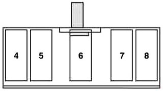
| № | Fused function | A |
|---|---|---|
| 4 | - | - |
| 5 | Valid as of 1.7.09: ESP control unit | 40 |
| 6 | Valid up to 30.6.09: ESP control unit | 40 |
| Valid as of 1.7.09: Electrohydraulic power steering | 100 | |
| 7 | AAC with integrated control additional fan motor | 100 |
| 8 | Engine compartment fuse and relay box | 150 |
Advertisements
Luggage Compartment Fuse Box
The fuse block is placed in the stowage well under the trunk floor.
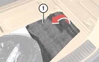
To open:
- Open the cargo compartment.
- Lift the cargo compartment cover.
- Secure cargo compartment cover with securing hook.
- Fold cover 1 to the left as indicated by the arrow.
To close:
- Install cover 1 in reverse order.
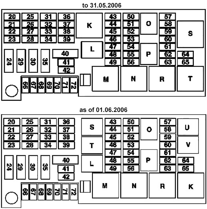
| № | Fused function | A |
|---|---|---|
| 20 | Interference suppression filter for radio antenna | 5 |
| Microphone array control unit (up to 2008; except Japan version) | ||
| Voice control system (VCS [SBS]) control unit (up to 2008; USA version) | ||
| 21 | RCP [HBF] control unit | 5 |
| 22 | Parktronic system (PTS) control unit | 5 |
| Stationary heater (STH) radio remote control receiver (as of 2009) | ||
| 23 | DVD player (rear entertainment system) | 10 |
| E-net compensator | ||
| Rear audio control unit (up to 2008) | ||
| Portable CTEL separation point (up to 2008; Japan version) | ||
| Universal Portable CTEL Interface (UPCI [UHI]) control unit (up to 2008; Japan version) | ||
| COMAND operating, display and controller unit (as of 2009) | ||
| 24 | Right front reversible emergency tensioning retractor | 40 |
| 25 | up to 2008: | 15 |
| Radio (except USA version and Japan version) | ||
| Radio and navigation unit (except USA version and Japan version) | ||
| COMAND operating, display and controller unit | ||
| as of 2009: | 20 | |
| Radio | ||
| Radio and navigation unit | ||
| COMAND operating, display and controller unit | ||
| 26 | Right front door control unit | 25 |
| 27 | Front passenger seat adjustment comfort relay (up to 2008) | 30 |
| Passenger-side front seat adjustment control unit with memory | ||
| 28 | Driver seat adjustment comfort relay (up to 2008) | 30 |
| Driver-side front seat adjustment control unit, with memory | ||
| 29 | Left front reversible emergency tensioning retractor | 40 |
| 30 | up to 2008: | 40 |
| Valid for engine 156: | ||
| Left fuel pump control unit | ||
| Right fuel pump control unit | ||
| as of 2009: Fuel system control unit | ||
| 31 | HS [SIH], seat ventilation and steering wheel heater control unit | 10 |
| 32 | AIRmatic with ADS control unit | 15 |
| Rear axle level control system control unit | ||
| 33 | Keyless Go control unit | 25 |
| 34 | Left front door control unit | 25 |
| 35 | Amplifier for sound system | 30 |
| Subwoofer amplifier (as of 2009) | ||
| 36 | up to 2008: Emergency call system control unit | 5 |
| up to 2008: | 10 | |
| Japan version: | ||
| VICS+ETC voltage supply separation point | ||
| as of 2009: Emergency call system control unit | ||
| 37 | Backup camera voltage supply module (as of 01.06.2006, except USA version and Japan version) | 5 |
| Backup camera control unit (as of 01.06.2006, Japan version) | ||
| 38 | Audio gateway control unit (up to 2008; Japan version) | 10 |
| Digital TV tuner | ||
| TV combination tuner (analog/digital) | ||
| 39 | up to 2008: | 7.5 |
| SDAR control unit (USA version) | ||
| Tire pressure monitor (TPM) [RDK] control unit | ||
| as of 2009: | ||
| Tire pressure monitor (TPM) [RDK] control unit | ||
| High definition tuner control unit | ||
| Digital Audio Broadcasting control unit | ||
| External navigation separating point (South Korea version) | ||
| 40 | up to 2008: Rear-end door closing control unit | 40 |
| as of 2009: Rear-end door closing control unit | 30 | |
| 41 | Overhead control panel control unit | 25 |
| 42 | Overhead control panel control unit | 25 |
| 43 | Up to 31.05.2006: | 20 |
| Tailgate wiper motor | ||
| Left 3rd seat row socket | ||
| Right 3rd seat row socket | ||
| as of 2009: | ||
| Valid for engine 272, 273, 276: Fuel system control unit | ||
| Valid for engine 642.872: Right fuel system control unit | ||
| 44 | Up to 31.05.2006: | 20 |
| Left 2nd seat row socket | ||
| Right 2nd seat row socket | ||
| as of 2009: | ||
| USA version: | ||
| Front interior socket | ||
| 115 V socket | ||
| 45 | up to 2008: | 20 |
| Cargo area connector box | ||
| up to 31.05.2006: | ||
| Front interior socket | ||
| as of 01.06.2006: | ||
| Left 2nd seat row socket | ||
| Right 2nd seat row socket | ||
| as of 2009: | ||
| Right 2nd seat row socket | ||
| Luggage compartment socket | ||
| 46 | Front cigar lighter with ashtray illumination | 15 |
| 47 | as of 2009: | 10 |
| Valid for retrofit: | ||
| Left front illuminated door sill molding | ||
| Right front illuminated door sill molding | ||
| 48 | as of 2009: | 5 |
| Valid for engine 642.870: AdBlue® supply relay | ||
| 49 | Right antenna coil (up to 2008) | 30 |
| Heated rear window | ||
| 50 | up to 2008: Tailgate wiper motor | 10 |
| as of 2009: Tailgate wiper motor | 15 | |
| 51 | Activated charcoal filter shutoff valve | 5 |
| 52 | up to 30.6.09: | 5 |
| Left front reversible emergency tensioning retractor | ||
| Right front reversible emergency tensioning retractor | ||
| 53 | AIRmatic with ADS control unit | 5 |
| Rear axle level control system control unit | ||
| up to 2008: | ||
| Valid for engine 156: | ||
| Left fuel pump control unit | ||
| Right fuel pump control unit | ||
| as of 2009: | ||
| Valid for engine 272, 273, 276: Fuel system control unit | ||
| Valid for engine 642.872: Right fuel system control unit | ||
| 54 | Front SAM control unit | 5 |
| Headlamp range adjustment control unit (bi-xenon headlamp unit) | ||
| 55 | Rotary light switch | 7.5 |
| Instrument cluster | ||
| 56 | up to 2008: Data link connector | 5 |
| as of 2009: | ||
| Valid for engine 642.870: AdBlue® control unit | ||
| 57 | up to 2008: Fuel pump with fuel gauge sensor | 20 |
| as of 2009: | ||
| Valid for engine 642.870: Fuel pump | ||
| 58 | Data link connector | 7.5 |
| Central gateway control unit | ||
| 59 | Driver NECK-PRO head restraint solenoid | 7.5 |
| Front passenger NECK-PRO head restraint solenoid | ||
| 60 | up to 2008: | 5 |
| Glove compartment illumination with switch | ||
| Rear SAM control unit | ||
| Engine compartment fuse and relay box | ||
| CTEL separation point | ||
| VICS+ETC voltage supply separation point (Japan version) | ||
| Emergency call system control unit | ||
| as of 2009: | ||
| Glove box illumination with switch | ||
| Engine compartment fuse and relay box | ||
| Rear SAM control unit) | ||
| Cell phone separation point | ||
| VICS+ETC power supply separating point (Japan version) | ||
| Multicontour seat pneumatic pump | ||
| External navigation separating point (South Korea version) | ||
| Emergency call system control unit | ||
| Rear bumper interior Blind Spot Monitoring electrical connector | ||
| 61 | Restraint systems control unit | 10 |
| Right front seat contacting strip | ||
| 62 | Front passenger seat adjustment switch | 30 |
| Front passenger lumbar support regulator control unit | ||
| 63 | Driver seat adjustment switch | 30 |
| Driver lumbar support regulator control unit | ||
| 64 | - | - |
| 65 | - | - |
| 66 | as of 2009: Multicontour seat pneumatic pump | 30 |
| 67 | Rear air conditioning blower motor | 25 |
| 68 | up to 2008: Heated rear seats | 25 |
| as of 2009: Seat heater, seat ventilation and steering wheel heater control unit | ||
| 69 | - | 30 |
| 70 | Trailer hitch socket (13-pin) | 20 |
| Trailer hitch socket (7-pin) (USA version) | ||
| 71 | USA version: Electric brake control separation point | 30 |
| 72 | Trailer hitch socket (13-pin) | 15 |
| K | to 31.05.2006: Terminal 15R power outlet relay, with power-down | |
| as of 01.06.2006: Relay, circuit 15R sockets (with power-down) (power supply of electric seat adjustment) | ||
| L | Terminal 30X | |
| M | Heated rear window relay | |
| N | Circuit 15 relay / terminal 87FW | |
| O | Fuel pump relay | |
| P | Rear wiper relay | |
| R | Circuit R relay 15R | |
| S | Reserve 1 (changer) (power supply for front socket) | |
| T | as of 01.06.2006: Reserve 2 (normally open contact) (power supply for center and rear sockets) | |
| U | as of 01.06.2006: Trailer relay terminal 30 | |
| V | as of 01.06.2006: Spare relay 2 | |
Advertisements