
Advertisements
Fuse box diagram (fuse layout), location, and assignment of fuses and relays Mercedes-Benz GLC-Class (X253, C253) (GLC 200, 220d, 250, 250d, 300, 350, 350d, 43 & 63 AMG) (2015, 2016, 2017, 2018, 2019).

Checking and Replacing Fuses
The fuses in your vehicle serve to close down faulty circuits. If a fuse blows, all the components on the circuit and their functions stop operating. If a fuse has blown, the inside element will be melted. Blown fuses must be replaced with fuses of the same rating, which you can recognize by the color and value. The fuse ratings are listed in the fuse allocation chart (It is on the fuse box in the cargo compartment).
If a newly inserted fuse also blows, have the cause traced and rectified at a qualified specialist workshop, e.g. an authorized Mercedes-Benz Center.
Notice
- Before changing a fuse, secure the vehicle against rolling away and switch off all electrical consumers.
- Always disconnect the battery before servicing high current fuses.
- Always replace faulty fuses with the specified new fuses having the correct amperage. If you manipulate or bridge a faulty fuse or if you replace it with a fuse with a higher amperage, the electric cables could be overloaded. This could result in a fire. There is a risk of an accident and injury.
- Only use fuses that have been approved for Mercedes-Benz vehicles and which have the correct fuse rating for the system concerned. Only use fuses marked with an “S”. Otherwise, components or systems could be damaged.
Dashboard Fuse Box
The fuse block is located on the driver’s side of the dashboard.
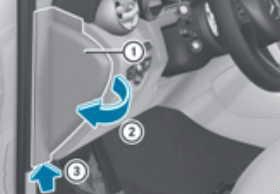
- Open the driver’s door.
- To open: pull out cover (1) slightly at the bottom in the direction of the arrow (3).
- Fold cover (1) outwards in the direction of the arrow (2).
- To close: fold in cover (1) until it engages.
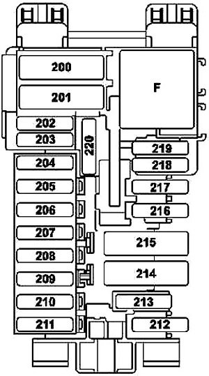
| № | Fused component | A |
|---|---|---|
| 200 | Front SAM control unit | 50 |
| 201 | Front SAM control unit | 40 |
| 202 | Alarm siren | 5 |
| 203 | Valid with transmission 716: Electric steering lock control unit | 20 |
| 204 | Diagnostic connector | 5 |
| 205 | Electronic ignition lock control unit | 7.5 |
| 206 | Analog clock | 5 |
| 207 | Climate control control unit | 15 |
| 208 | Instrument cluster | 7.5 |
| 209 | Climate control operating unit | 5 |
| Upper control panel control unit | ||
| 210 | Steering column tube module control unit | 10 |
| 211 | Spare | 25 |
| 212 | Spare | 5 |
| 213 | Electronic Stability Program control unit | 5 |
| 214 | Spare | 30 |
| 215 | Spare | - |
| 216 | Glove compartment lamp | 7.5 |
| 217 | Japan version: Dedicated Short-Range Communications control unit | 5 |
| 218 | Supplemental Restraint System control unit | 7.5 |
| 219 | Weight sensing system (WSS) control unit | 5 |
| 220 | Spare | - |
| F | Relay, circuit 15R | |
Advertisements
Front-Passenger Footwell Fuse Box
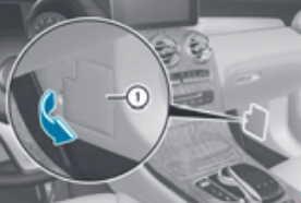
- Open the front-passenger door.
- To open: fold cover (1) out towards the rear and remove it.
- To close: clip in cover (1) at the rear.
- Fold cover (1) forwards until it engages.
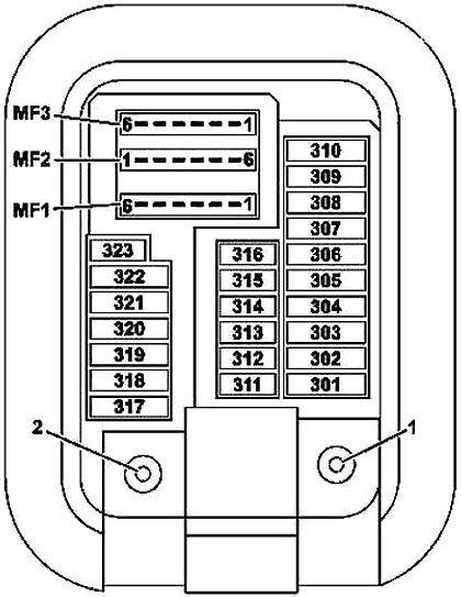
| № | Fused component | A |
|---|---|---|
| 301 | Hybrid: Pyrofuse via high-voltage disconnect device | 5 |
| 302 | Right front door control unit | 30 |
| 303 | Left rear door control unit | 30 |
| 304 | Valid for transmission 722: Intelligent servo module for DIRECT SELECT (A80) | 20 |
| 305 | Driver seat control unit | 30 |
| Driver seat heater control unit | ||
| Front seat heater control unit | ||
| 306 | Front passenger seat control unit | 30 |
| Front passenger seat heater control unit | ||
| Front seat heater control unit | ||
| 307 | Spare | - |
| 308 | USA version: Electric Brake Control electrical connector | 30 |
| 309 | Emergency call system control unit | 10 |
| HERMES control unit | 5 | |
| Telematics services communications module | ||
| 310 | Spare | - |
| 311 | Booster blower electronic blower regulator | 10 |
| 312 | Overhead control panel control unit | 10 |
| 313 | Hybrid: DC/DC converter control unit | 10 |
| 314 | Spare | - |
| 315 | Powertrain control unit | 5 |
| Valid for diesel engine: CDI control unit | ||
| Valid for gasoline engine: ME-SFI control unit | ||
| 316 | Supplemental Restraint System control unit | 7.5 |
| 317 | Panoramic sliding sunroof control module | 30 |
| Sliding roof control module | ||
| 318 | Stationary heater control unit | 20 |
| 319 | Hybrid: High-voltage PTC heater | 5 |
| 320 | AIR BODY CONTROL control unit | 15 |
| 321 | Japan version: Dedicated Short-Range Communications control unit | 5 |
| 322 | Head unit | 20 |
| 323 | Parking system control unit | 5 |
| MF1/1 | Audio/COMAND display | 7.5 |
| Audio equipment fan motor | ||
| MF1/2 | Stereo multifunction camera | 7.5 |
| Mono multifunction camera | ||
| MF1/3 | Rain/light sensor with additional functions | 7.5 |
| Overhead control panel control unit | ||
| MF1/4 | Driver seat control unit | 7.5 |
| Driver seat heater control unit | ||
| Front seat heater control unit | ||
| MF1/5 | Front passenger seat control unit | 7.5 |
| Front passenger seat heater control unit | ||
| Front seat heater control unit | ||
| MF1/6 | Steering column tube module control unit | 7.5 |
| MF2/1 | Left front reversible emergency tensioning retractor | 5 |
| MF2/2 | Audio/COMAND control panel | 5 |
| Touchpad | ||
| MF2/3 | Right front reversible emergency tensioning retractor | 5 |
| MF2/4 | Heads-up display | 5 |
| MF2/5 | Multimedia connection unit | 5 |
| MF2/6 | Hybrid: Electrical refrigerant compressor | 5 |
| MF3/1 | Feedback line, terminal 30g, front SAM control unit | 5 |
| MF3/2 | Radar sensors control unit | 5 |
| MF3/3 | Spare | - |
| MF3/4 | Driver side instrument panel button group | 5 |
| MF3/5 | Rear air conditioning operating unit | 5 |
| MF3/6 | Tire pressure monitor control unit |
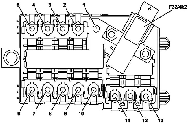
Interior prefuse box
| № | Fused component | A |
|---|---|---|
| 1 | Engine compartment prefuse box | - |
| 2 | Hybrid: Additional battery relay for ECO start/stop function | 150 |
| 3 | Blower regulator | 40 |
| 4 | Spare | - |
| 5 | Valid for diesel engine: PTC heater booster | 150 |
| 6 | Right A-pillar fuse box | 80 |
| 7 | Rear fuse and relay module | 150 |
| 8 | Spare | - |
| 9 | Spare | - |
| 10 | Valid for transmission 725 (except GLC 350 e 4Matic): Fully integrated transmission control unit | 60 |
| GLC 350 e 4Matic: Fully integrated transmission control unit | 100 | |
| 11 | Spare | - |
| 12 | Rear fuse and relay module | 40 |
| 13 | Right A-pillar fuse box | 50 |
| F32/4k2 | Quiescent current cutout relay |
Advertisements
Engine Compartment Fuse Box
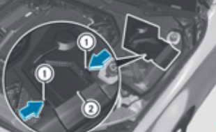
- Open the hood.
- To open: press safety clips (1) on the cover together.
- Remove fuse box cover (2) upwards.
- Use a dry cloth to remove any moisture from the fuse box.
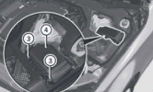
- Loosen screws (3), fold up fuse box lid (4) and remove it.
- To close: check whether the seal is positioned correctly in the lid (4).
- Insert lid (4) into the bracket at the rear of the fuse box.
- Fold-down lid (4) of the fuse box and tighten screws (3).
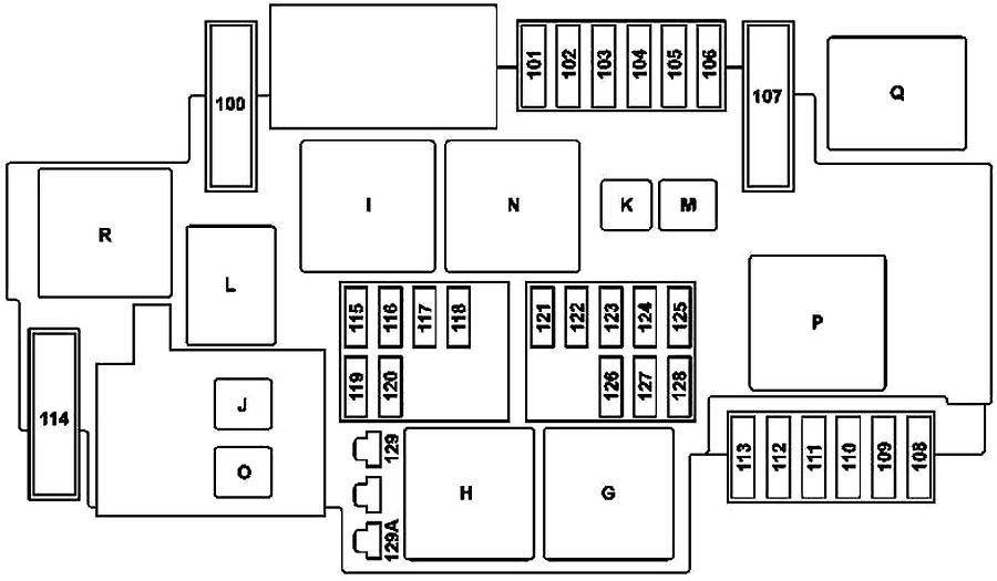
| № | Fused component | A |
|---|---|---|
| 100 | Hybrid: Vacuum pump | 40 |
| 101 | Connector sleeve, circuit 87/2 | 15 |
| 102 | Connector sleeve, circuit 87/1 | 20 |
| 103 | Connector sleeve, circuit 87/4 | 15 |
| 104 | Connector sleeve, circuit 87/3 | 15 |
| 105 | Valid for transmission 722.9 (except 722.930): Automatic transmission fluid auxiliary oil pump control unit | 15 |
| 106 | Spare | - |
| 107 | Valid with engine 274.9: Electric coolant pump | 60 |
| 108 | Static LED headlamp: Right front lamp unit | 20 |
| High performance LED, Dynamic LED headlamp: | ||
| Left front lamp unit | ||
| Right front lamp unit | ||
| 109 | Wiper motor | 30 |
| 110 | Static LED headlamp: Left front lamp unit | 20 |
| High performance LED, Dynamic LED headlamp: | ||
| Left front lamp unit | ||
| Right front lamp unit | ||
| 111 | Starter | 30 |
| 112 | Hybrid: Accelerator pedal sensor | 15 |
| 113 | Spare | - |
| 114 | AIR BODY CONTROL compressor | 40 |
| 115 | Left horn and right horn | 15 |
| 116 | Spare | - |
| 117 | Spare | - |
| 118 | Hybrid: Electronic Stability Program control unit | 5 |
| 119 | Circuit 87 C2 connector sleeve | 15 |
| 120 | Circuit 87 C1 connector sleeve | 5 |
| 121 | Electronic Stability Program control unit | 5 |
| 122 | CPC relay | 5 |
| 123 | Spare | - |
| 124 | Spare | - |
| 125 | Front SAM control unit | 5 |
| 126 | Powertrain control unit | 5 |
| Valid for diesel engine: CDI control unit | ||
| Valid for gasoline engine: ME-SFI control unit | ||
| 127 | Hybrid: Voltage dip limiter | 5 |
| 128 | Left front lamp unit and exterior lights switch | 5 |
| 129 | Hybrid: Starter circuit 50 relay | 30 |
| 129A | Hybrid: Starter circuit 50 relay | 30 |
| G | Engine compartment circuit 15 relay | |
| H | Starter circuit 50 relay | |
| I | Hybrid: Vacuum pump relay (+) | |
| J | CPC relay | |
| K | Valid for transmission 722.9 (except 722.930): Oil pump relay | |
| L | Horn relay | |
| M | Wiper park position heater relay | |
| N | Circuit 87M relay | |
| O | Hybrid: Starter circuit 15 relay | |
| P | Valid with engine 274.9: Coolant pump relay | |
| Q | Hybrid: Vacuum pump relay (-) | |
| R | AIR BODY CONTROL relay | |
Prefuse Box in the Engine Compartment
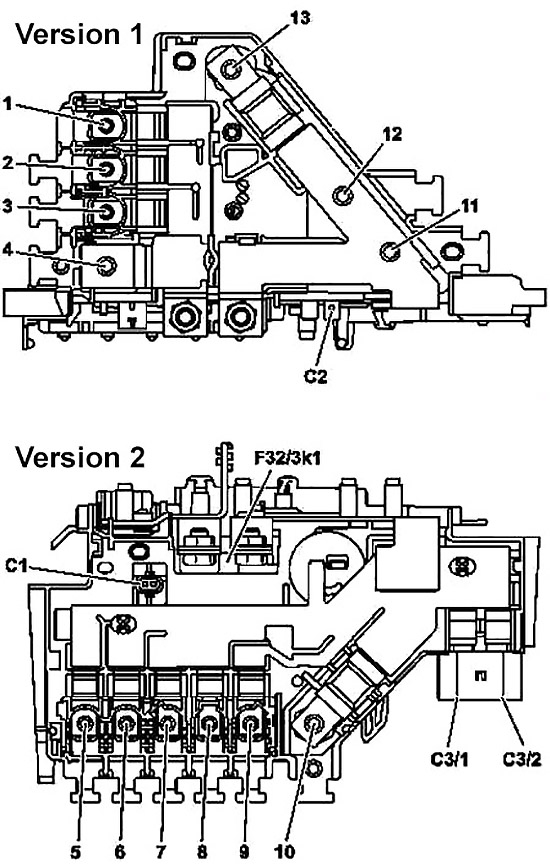
| № | Fused component | A |
|---|---|---|
| 1 | Spare | - |
| 2 | Valid for diesel engine: Glow output stage | 100 |
| 3 | Engine fuse and relay module | 60 |
| 4 | On-board electrical system battery connection | - |
| 5 | Engine fuse and relay module | 150 |
| 6 | Left fuse and relay module | 125 |
| 7 | Fan motor (600 W / 850 W) | 80 |
| 8 | Electrical power steering control unit | 125 |
| 9 | Fan motor (1000 W) | 150 |
| 10 | Vehicle interior prefuse box | 200 |
| 11 | Spare | - |
| 12 | Hybrid: Power electronics control unit | - |
| With engine 651.9 and USA version: Catalytic converter heater control unit | ||
| 13 | Alternator | 400 |
| C1 | Hybrid: Decoupling relay | - |
| C2 | Hybrid: Circuit 31 | - |
| C3/1 | Electronic Stability Program control unit | 40 |
| C3/2 | Electronic Stability Program control unit | 60 |
| F32/3k1 | Decoupling relay |
Advertisements
Luggage Compartment Fuse Box
It is under the cargo compartment floor on the right-hand side of the vehicle, when viewed in the direction of travel.
The fuse allocation chart is located in a recess at the side of the fuse box. You can find the corresponding fuse rating and fuse type on the fuse allocation chart.
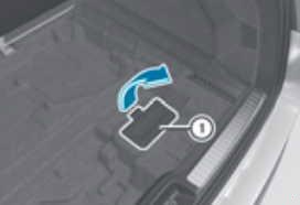
- Open the tailgate.
- Lift the cargo compartment floor upwards.
- To open: release cover at the top and open it (1) downwards in the direction of the arrow.
- To close: fold-down cover (1) in the opposite direction to the arrow and close the Velcro fastener.
- Make sure that the cover is in the recess provided for it.
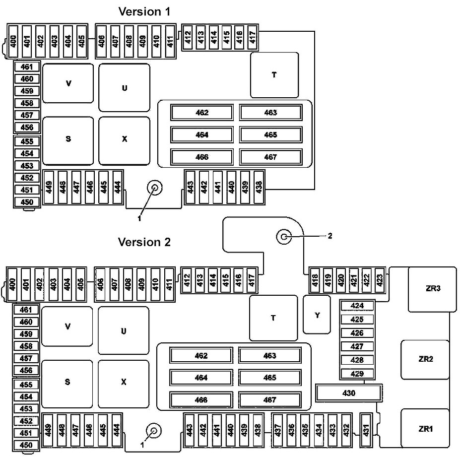
| № | Fused component | A |
|---|---|---|
| 400 | BlueTEC: AdBlue control unit | 25 |
| 401 | BlueTEC: AdBlue control unit | 15 |
| 402 | BlueTEC: AdBlue control unit | 20 |
| 403 | Valid up to 30.11.2015: Front passenger seat partially electric seat adjustment switch | 30 |
| Valid as of 01.12.2015: Front passenger seat partially electric seat adjustment switch | 25 | |
| 404 | Valid up to 30.11.2015: Driver seat partially electric seat adjustment switch | 30 |
| Valid as of 01.12.2015: Driver seat partially electric seat adjustment switch | 25 | |
| 405 | Spare | - |
| 406 | Left front door control unit | 30 |
| 407 | Spare | - |
| 408 | Right rear door control unit | 30 |
| 409 | Spare | - |
| 410 | Stationary heater radio remote control receiver | 5 |
| Antenna changeover switch for telephone and stationary heater | ||
| 411 | Left front reversible emergency tensioning retractor | 30 |
| 412 | Hybrid: Battery management system control unit | 7.5 |
| 413 | Trunk lid control control unit | 5 |
| 414 | Tuner unit | 5 |
| 415 | Camera cover control unit | 5 |
| Perfume atomizer generator | ||
| 416 | Cellular telephone system antenna amplifier/compensator | 7.5 |
| Mobile phone contact plate | ||
| 417 | 360° camera control unit | 5 |
| Reversing camera | ||
| 418 | Rear seat heater control unit | 5 |
| AIRSCARF control unit | ||
| 419 | Front passenger seat lumbar support adjustment control unit | 5 |
| 420 | Driver seat lumbar support adjustment control unit | 5 |
| 421 | Spare | - |
| 422 | Spare | - |
| 423 | Sound system amplifier control unit | 5 |
| 424 | AIR BODY CONTROL Plus control unit | 15 |
| Valid for engine 276: Engine sound control unit | ||
| 425 | Spare | - |
| 426 | Spare | - |
| 427 | Spare | - |
| 428 | Spare | - |
| 429 | Spare | - |
| 430 | Spare | - |
| 431 | Special-purpose vehicle multifunction control unit | 25 |
| 432 | Special-purpose vehicle multifunction control unit | 25 |
| 433 | Trailer recognition control unit | 20 |
| 434 | Trailer recognition control unit | 30 |
| 435 | Trailer recognition control unit | 25 |
| 436 | Trailer recognition control unit | 15 |
| 437 | Trailer recognition control unit | 25 |
| 438 | DC/AC converter control unit | 30 |
| 439 | Spare | - |
| 440 | Rear seat heater control unit | 30 |
| AIRSCARF control unit | ||
| 441 | AIRSCARF control unit | 30 |
| 442 | Fuel system control unit | 25 |
| 443 | Right front reversible emergency tensioning retractor | 30 |
| 444 | Tablet PC electrical connector | 15 |
| 445 | Luggage compartment socket | 15 |
| 446 | Front cigarette lighter with ashtray illumination | 15 |
| Vehicle interior power outlet | ||
| 447 | Right rear center console socket 12V | 15 |
| 448 | Valid for transmission 722, 725: Park pawl capacitor | 10 |
| 449 | Valid for engine 626: Fuel filter element with integrated heater | 5 |
| Hybrid: Sound generator | ||
| 450 | Rear SAM control unit | 5 |
| 451 | Fuel system control unit | 5 |
| BlueTEC: AdBlue control unit | ||
| 452 | Integrated outer right rear bumper radar sensor | 5 |
| Integrated outer left rear bumper radar sensor | ||
| Center rear bumper radar sensor | ||
| Outer right rear bumper radar sensor | ||
| Outer left rear bumper radar sensor | ||
| 453 | Left front bumper radar sensor | 5 |
| Right front bumper radar sensor | ||
| COLLISION PREVENTION ASSIST controller unit | ||
| 454 | Valid for transmission 722: Fully integrated transmission control unit | 7.5 |
| BlueTEC: AdBlue control unit | 5 | |
| 455 | DC/AC converter control unit | 5 |
| 456 | Front long-range radar sensor | 5 |
| DISTRONIC electric controller unit | ||
| 457 | Hybrid: | 5 |
| Power electronics control unit | ||
| DC/DC converter control unit | ||
| Power electronics control unit | ||
| 458 | Rear switching module | 5 |
| 459 | Hybrid: Charger | 5 |
| 460 | KEYLESS-GO control unit | 10 |
| 461 | FM 1, AM, CL [ZV] and KEYLESS-GO antenna amplifier | 5 |
| 462 | Sound system amplifier control unit | 40 |
| 463 | Rear window heater via rear window interference suppression capacitor | 30 |
| 464 | Trunk lid control control unit | 40 |
| Liftgate control control unit | ||
| 465 | Rear SAM control unit | 40 |
| 466 | Rear SAM control unit | 40 |
| 467 | Valid for engine 626: Fuel filter element with integrated heater | 40 |
| S | Vehicle interior circuit 15 relay | |
| T | Rear window heater relay | |
| U | 2nd seat row cup holder and sockets relay | |
| V | BlueTEC: AdBlue relay | |
| X | 1 st seat row/trunk refrigerator box and sockets relay | |
| Y | Spare relay | |
| ZR1 | Valid for engine 626: Fuel filter heater relay | |
| ZR2 | Reserve relay | |
| ZR3 | Reserve relay | |
Advertisements