
Advertisements
Fuse box diagram (fuse layout), location, and assignment of fuses and relays Mercedes-Benz C-Class – C180, C200, C220, C230, C240, C270, C280, C320, C350, C30 AMG, C32 AMG, C55 AMG (W203) (2000, 2001, 2002, 2003, 2004, 2005, 2006, 2007).
Checking and Replacing Fuses
The fuses in your vehicle serve to close down faulty circuits. If a fuse blows, all the components on the circuit and their functions stop operating. If a fuse has blown, the inside element will be melted. Blown fuses must be replaced with fuses of the same rating, which you can recognize by the color and value.
If a newly inserted fuse also blows, have the cause traced and rectified at a qualified specialist workshop, e.g. an authorized Mercedes-Benz Center.
Notice
- Before changing a fuse, secure the vehicle against rolling away and switch off all electrical consumers.
- Always disconnect the battery before servicing high current fuses.
- Always replace faulty fuses with the specified new fuses having the correct amperage. If you manipulate or bridge a faulty fuse or if you replace it with a fuse with a higher amperage, the electric cables could be overloaded. This could result in a fire. There is a risk of an accident and injury.
- Only use fuses that have been approved for Mercedes-Benz vehicles and which have the correct fuse rating for the system concerned. Only use fuses marked with an “S”. Otherwise, components or systems could be damaged.
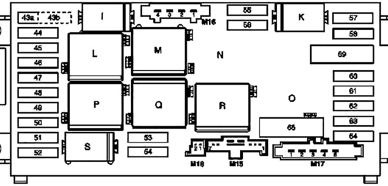
Instrument Panel Fuse Box
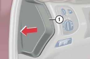
- Pull cover (1) open with a screwdriver or a similar tool.
- Remove cover rearward.
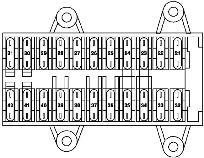
| № | Circuit protected | A |
|---|---|---|
| 21 | Left front door control unit | 30 |
| 22 | Right front door control unit | 30 |
| 23 | Up to 30.11.04: Central gateway control unit | 15 |
| 24 | CD player with changer (in glove compartment) | 7.5 |
| 25 | Upper control panel control unit | 30 |
| 26 | Sound amplifier | 25 |
| 27 | Driver-side front seat adjustment control unit, with memory | 30 |
| Special vehicle multifunction control unit (SVMCU [MSS]) | ||
| 28 | Spare | 30 |
| 29 | Driver-side front seat adjustment control unit, with memory | 30 |
| Driver-side front seat adjustment control unit, with memory | ||
| Special vehicle multifunction control unit | ||
| 30 | Heating systems recirculation unit | 40 |
| 31 | EIS [EZS] control unit | 20 |
| Electric steering lock control unit | ||
| 32 | Left rear door control unit | 30 |
| 33 | Right rear door control unit | 30 |
| 34 | Cell phone separation point | 7.5 |
| up to 31.5.01: | ||
| Telephone and TELE AID transmitter/receiver, D2B | ||
| Telephone transmitter and receiver unit, D2B | ||
| Telephone interface | ||
| E-net compensator | ||
| up to 31.5.01, Japan version: E-call control unit | ||
| up to 31.3.04: Front passenger front seat adjustment control unit with memory | 15 | |
| as of 1.4.04: Passenger-side front seat adjustment control unit with memory | ||
| up to 31.5.03, Taxi: Special vehicle multifunction control unit | ||
| as of 1.6.03, Taxi: Special vehicle multifunction control unit | ||
| as of 1.6.01, Police: Special vehicle multifunction control unit | ||
| as of 1.4.04: Front passenger front seat adjustment control unit with memory | 30 | |
| as of 1.4.04, Taxi: Special vehicle multifunction control unit | ||
| 35 | up to 31.3.04: STH heater unit | 30 |
| as of 1.4.04: STH heater unit | 20 | |
| 36 | up to 31.3.04, Police: Interior socket | 30 |
| Valid for engine (612.990) (up to 29.2.04): Charge air cooler circulation pump | 15 | |
| as of 1.4.04, Japan version: Audio gateway control unit | ||
| Universal Portable CTEL Interface (UPCI [UHI]) control unit | 7.5 | |
| 37 | Charge air cooler circulation pump | 25 |
| up to 29.2.04: Brake booster vacuum pump control unit | ||
| 38 | up to 29.2.04:Passenger-side front seat adjustment control unit with memory | 30 |
| as of 1.4.04, Police:Special vehicle multifunction control unit (SVMCU [MSS]) | ||
| 39 | Spare | 30 |
| 40 | Passenger-side front seat adjustment control unit with memory | 7.5 |
| Universal Portable CTEL Interface (UPCI [UHI]) control unit | ||
| Cell phone separation point | ||
| Telephone interface | ||
| E-net compensator | ||
| as of 1.6.01, MB standard telephone: Telephone transmitter and receiver unit, D2B | ||
| as of 1.6.01, TELE AID: Telephone and TELE AID transmitter/receiver, D2B | ||
| as of 1.6.01, Canadian vehicles: Via the trunk lid/FFS [RBA] separation point the trunk lid emergency release switch and the rear SAM control unit with fuse and relay module | ||
| USA version: Via the trunk lid/FFS [RBA] separation point the trunk lid emergency release switch and the rear SAM control unit with fuse and relay module | ||
| as of 1.4.04, Japan version: E-call control unit | ||
| up to 31.5.01: Special vehicle multifunction control unit | 30 | |
| 41 | HEAT control and operating unit | 7.5 |
| up to 31.5.01: | ||
| AAC [KLA] control and operating unit | ||
| Comfort AAC [kLa] control and operating unit | ||
| as of 1.6.01: | 15 | |
| AAC [KLA] control and operating unit | ||
| Comfort AAC [KLA] control and operating unit | ||
| 42 | Instrument cluster | 7.5 |
Advertisements
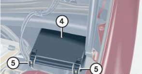
Engine Compartment Fuse Box
The fuse box is located in the engine compartment on the left-hand side.
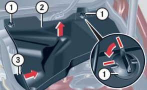
- Twist screws (1) 90° counterclockwise.
- Pull up cover (2)
- Slide-out retainer (3) and remove the cover by pulling towards the front.
- Install cover (2) in reverse order.
- Release clamps (5)
- Remove cover (4)
| № | Circuit protected | A |
|---|---|---|
| 43a | Fanfare horn relay | 15 |
| 43b | Fanfare horn relay | 15 |
| 44 | Telephone and TELE AID transmitter/ receiver, D2B | 5 |
| Telephone transmitter and receiver unit, D2B | ||
| Cell phone separation point | ||
| 45 | Restraint systems control unit | 7.5 |
| 46 | Wiper ON/OFF relay | 40 |
| Wiper speed 1 and 2 relay | ||
| 47 | Glove compartment illumination with switch | 15 |
| Front cigar lighter (with illumination) | ||
| 48 | Valid for engine 612.990 (up to 31.3.04): Brake booster vacuum pump control unit | 15 |
| Valid for engine 112 and engine 113: Circuit 15 connector sleeve (fused) | ||
| Valid for engine 646, USA version (up to 31.3.04): Circuit 30 connector sleeve | ||
| Valid for engine 646 (as of 1.4.04): O2 sensor upstream of TWC [kAt] connector | ||
| 49 | Restraint systems control unit | 7.5 |
| 50 | Light switch module | 5 |
| Valid for engine 612.990 | ||
| Glow output stage (up to 31.3.04) | ||
| Hot film mass air flow sensor (1.4.04 up to 30.11.04) | ||
| 51 | AAC with integrated control additional fan motor | 7.5 |
| Instrument cluster | ||
| Valid for code (581) comfort automatic air conditioning: | ||
| C-AAC [K-KLA] multifunction sensor | ||
| C-AAC [K-KLA] sun sensor (4 in total) | ||
| Left front lamp unit | ||
| Right front lamp unit | ||
| Valid for AMG vehicles: Charge air cooler circulation pump | ||
| Valid for model 203.0 (up to 31.7.01): SPS [PML] control unit | ||
| 52 | Starter | 15 |
| 53 | Valid for diesel engines: | |
| Starter relay | 25 | |
| Rear SAM control unit with fuse and relay module | ||
| Valid for engine 611/612/642/646: CDI control unit | ||
| Valid for gasoline engines: | 15 | |
| Starter relay | ||
| Rear SAM control unit with fuse and relay module | ||
| Valid for engine 111/271/272: ME-SFI [ME] control unit | ||
| Valid for engine 112/113: | ||
| ME-SFI [ME] control unit | ||
| Circuit 87M1e connector sleeve | ||
| 54 | Valid for engine 271.940: | 15 |
| ME-SFI [ME] control unit | ||
| Purge control valve (USA version) | ||
| Activated charcoal canister shutoff valve | ||
| Valid for engine 271.942: NOX (nitrogen oxides) control unit | ||
| Valid for engine 642/646: CDI control unit | ||
| Valid for engine 642/646: Circuit 30 connector sleeve | ||
| Valid for engines 611/612: CDI control unit | 7.5 | |
| Valid for engine 611/612 (up to 30.11.04): Vent line heater element | ||
| 55 | Steering angle sensor | 7.5 |
| Distronic: DTR control unit | ||
| Valid for transmission 722: | ||
| ETC [EGS] control unit (up to 31.5.04) | ||
| Electronic selector lever module control unit | ||
| Electric controller unit (VGS) | ||
| Valid for transmission 716: | ||
| Gear recognition switch | ||
| Automated manual transmission control unit | ||
| 56 | ESP and BAS control unit | 5 |
| Stop light switch | ||
| 57 | Steering angle sensor (up to 31.5.02) | 5 |
| EIS [EZS] control unit | ||
| Steering column module (as of 1.6.02) | ||
| Valid for engine 112/113: ME-SFI [ME] control unit | ||
| 58 | Valid for transmission 716: SEQ hydraulic pump | 40 |
| 59 | ESP and BAS control unit | 50 |
| 60 | ESP and BAS control unit | 40 |
| 61 | Valid for transmission 716: Automated manual transmission control unit | 15 |
| 62 | Data link connector | 5 |
| Light switch module | ||
| Stop light switch | ||
| 63 | Light switch module | 5 |
| 64 | Radio | 10 |
| Radio and navigation unit | ||
| COMAND operating, display and control unit | ||
| 65 | Valid for engine 112/113: Electric air pump | 40 |
| I | Fanfare horn system relay | |
| K | Terminal 87 relay, chassis | |
| L | Wiper speed 1 and 2 relay | |
| M | Terminal 15R relay | |
| N | SEQ [ASG] pump control relay (with Sequentronic automated manual transmission (ASG)) | |
| O | Air pump relay (engines 112, 113, 271 only) | |
| P | Terminal 15 relay | |
| Q | Wiper ON/OFF relay | |
| R | Terminal 87 relay, engine | |
| S | Starter relay | |
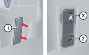
Front prefuse box
| № | Circuit protected | A |
|---|---|---|
| 1 | Interior fuse box | 125 |
| 2 | Rear SAM control unit with fuse and relay module | 200 |
| 3 | Additional fuse holder l, spare wheel well | 125 |
| 4 | Front SAM control unit with fuse and relay module | 200 |
| 5 | Engine and AC electric suction fan with integrated control | 125 |
| Valid for diesel engines: Glow output stage | ||
| 6 | Front SAM control unit with fuse and relay module | 60 |
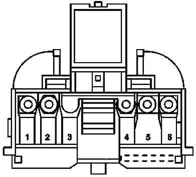
Luggage Compartment Fuse Box
It is on the left-hand side of the trunk.
- Trim panel
- Cover of auxiliary fuse box
- Special fuse extractor
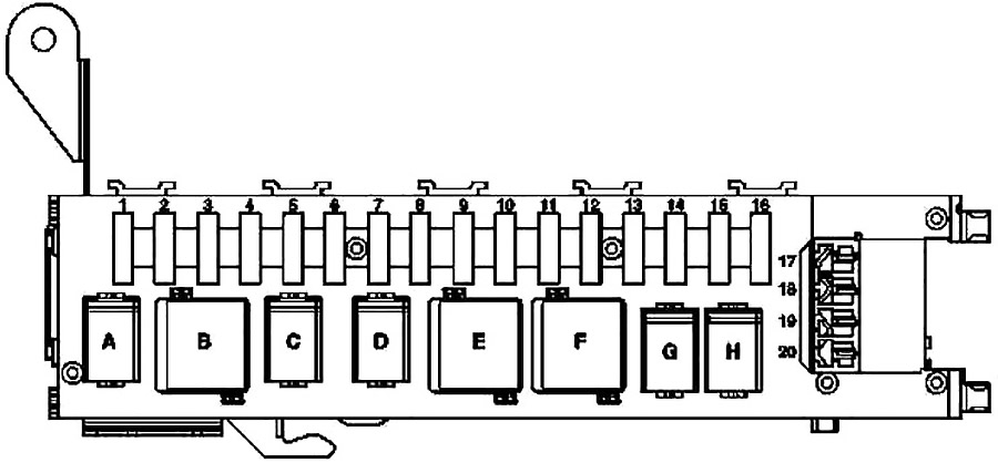
| № | Circuit protected | A |
|---|---|---|
| 1 | Front passenger front seat adjustment control unit with memory | 30 |
| Front passenger partially-electric seat adjustment switch | ||
| 2 | Driver front seat adjustment control unit with memory | 30 |
| Driver partially-electric seat adjustment switch | ||
| 3 | Dome lamp | 7.5 |
| Right luggage compartment lamp | ||
| Left luggage compartment lamp | ||
| STH radio remote control receiver | ||
| TV tuner (up to 29.2.04) | 20 | |
| TV tuner (MOST) (as of 1.4.04) | ||
| 4 | Fuel pump relay (N10/2kA) | 20 |
| 5 | Valid for engine 112.961 (up to 31.3.04): Charge air cooler circulation pump | 20 |
| Valid without engine 112.961: Backup relay 2 | ||
| 6 | Spare | 25 |
| 7 | Backup relay 1 | 7.5 |
| 8 | Amplifier module, window antenna | 7.5 |
| Alarm signal horn (H3) ATA [EDW] inclination sensor | ||
| 9 | Overhead control panel control unit | 25 |
| 10 | Heated rear window | 40 |
| 11 | Spare | 20 |
| 12 | Interior socket | 15 |
| Valid for model 203.0 USA version (up to 31.3.04): Power outlet | ||
| 13 | Multicontour seat pneumatic pump | 5 |
| Voice control system control unit | ||
| Rear dome lamp | ||
| Rear dome lamp PTS warning indicator | ||
| PTS control unit | ||
| Japan version: VICS+ETC voltage supply separation point. | ||
| 14 | Tailgate wiper motor | 15 |
| 15 | Fuel filler cap polarity change relay 1 | 10 |
| Fuel filler cap polarity change relay 2 | ||
| 16 | Voice control system control unit | 20 |
| 17 | Trailer recognition control unit | 20 |
| 18 | Trailer hitch socket (13-pin) | 20 |
| 19 | Multicontour seat pneumatic pump | 20 |
| 20 | Rear window roller blind relay | 15 |
| Valid for model 203.2/7 USA version: Power outlet | ||
| A | Fuel pump relay | |
| B | Relay 2, terminal 15R | |
| C | Reserve relay 2 | |
| D | Reserve relay 1 | |
| E | Rear window defroster relay | |
| F | Relay 1, terminal 15R | |
| G | Filler cap relay, polarity reverser 1 | |
| H | Filler cap relay, polarity reverser 2 | |
Advertisements