
Advertisements
Fuse box diagram (fuse layout), location, and assignment of fuses and relays Mercedes-Benz B-Class B160, B180, B200, B220, B250 and Electric Drive (W246, W242) (2011, 2012, 2013, 2014, 2015, 2016, 2017, 2018.

Checking and Replacing Fuses
The fuses in your vehicle serve to close down faulty circuits. If a fuse blows, all the components on the circuit and their functions stop operating. If a fuse has blown, the inside element will be melted. Blown fuses must be replaced with fuses of the same rating, which you can recognize by the color and value. The fuse ratings are listed in the fuse allocation chart (It is on the fuse box in the front-passenger footwell).
If a newly inserted fuse also blows, have the cause traced and rectified at a qualified specialist workshop, e.g. an authorized Mercedes-Benz Center.
Notice
- Before changing a fuse, secure the vehicle against rolling away and switch off all electrical consumers.
- Always disconnect the battery before servicing high current fuses.
- Always replace faulty fuses with the specified new fuses having the correct amperage. If you manipulate or bridge a faulty fuse or if you replace it with a fuse with a higher amperage, the electric cables could be overloaded. This could result in a fire. There is a risk of an accident and injury.
- Only use fuses that have been approved for Mercedes-Benz vehicles and which have the correct fuse rating for the system concerned. Only use fuses marked with an “S”. Otherwise, components or systems could be damaged.
Passenger Compartment Fuse Box
The fuse box is located in the front-passenger foot-well.
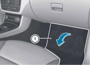
- To open: open the front-passenger door.
- Remove the floormat.
- Fold-out perforated floor covering (1) in the direction of the arrow.
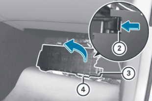
- To release cover (3), press retaining clamp (2).
- Fold-out cover (3) in the direction of the arrow to the catch.
- Remove cover (3) forwards.
Fuse allocation chart (4) is located on the lower right-hand side of the cover (3). - To close: insert cover (3) on the left-hand side of the fuse box into the retainer. Cover (3) engages in the retainers.
- Fold-down cover (3) until clamps (2) lock audibly.
- Fold back the perforated floor covering (1).
- Install the floormats.
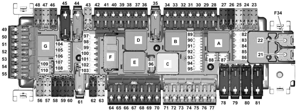
| № | Fused function | A |
|---|---|---|
| 21 | Valid for diesel engine: PTC heater booster | 150 |
| 22 | Additional battery relay for ECO start/stop function | 200 |
| 23 | Left front door control unit | 30 |
| 24 | Right front door control unit | 30 |
| 25 | SAM control unit | 30 |
| 26 | ECO start/stop additional battery connector sleeve | 10 |
| 27 | Engine compartment fuse and relay module | 30 |
| 28 | Vehicle interior sound generator control unit | 5 |
| Electric Drive (W242): Thermal management control unit | ||
| 29 | up to 02.11.2014: Trailer socket | 15 |
| as of 03.11.2014: Trailer recognition control unit | ||
| 30 | Trailer recognition control unit | 5 |
| 31 | 4MATIC: All-wheel drive control unit | 5 |
| 32 | Steering column tube module control unit | 5 |
| 33 | Audio/COMAND control panel | 5 |
| 34 | ACC control and operating unit | 7.5 |
| 35 | Rear window heater | 40 |
| 36 | Driver seat control unit | 7.5 |
| Driver seat lumbar support adjustment control unit | ||
| 37 | Audio/COMAND display | 7.5 |
| 38 | Supplemental Restraint System control unit | 7.5 |
| 39 | Overhead control panel control unit | 10 |
| 40 | Valid for engine 651 (Emissions standard EU6): Powertrain control unit | 15 |
| Electric Drive (W242): Powertrain control unit | 5 | |
| 41 | Panoramic sliding sunroof control module | 30 |
| 42 | Radio (Audio 5 USB, Audio 20 CD, Audio 20 CD with CD changer) | 5 |
| COMAND controller unit | ||
| Radio (Radio 20, Audio 20 USB) | 25 | |
| 43 | Parking system control unit | 5 |
| 44 | Left front reversible emergency tensioning retractor | 40 |
| 45 | Right front reversible emergency tensioning retractor | 40 |
| 46 | Front passenger seat control unit | 7.5 |
| Front passenger seat lumbar support adjustment control unit | ||
| 47 | Navigation module | 7.5 |
| Adaptive damping system control unit | 25 | |
| 48 | Spare | - |
| 49 | Control unit for Drive Kit for iPhone® | 7.5 |
| COMAND fan motor | 5 | |
| 50 | Spare | - |
| 51 | Spare | - |
| 52 | Electric Drive (W242): Park pawl actuator motor | 30 |
| 53 | Spare | - |
| 54 | Spare | - |
| 55 | Telematics services communications module | 5 |
| KEYLESS-GO control unit | ||
| 56 | Steering column tube module control unit | 10 |
| 57 | Lane Keeping Assist: Special-purpose vehicle multifunction control unit | 30 |
| Special vehicle: Special-purpose vehicle multifunction control unit | 7.5 | |
| Electric Drive (W242): Park pawl actuator motor circuit 87 relay (F34kG) | 5 | |
| 58 | Emergency vehicle fuse box | 30 |
| 59 | Front passenger seat control uni | 30 |
| 60 | Driver seat control unit | 30 |
| 61 | Sound system amplifier control unit | 40 |
| 62 | Valid for transmission 711: Electric steering lock control unit | 20 |
| 63 | Fuel system control unit | 25 |
| Electric Drive (W242): Gateway powertrain control unit | 5 | |
| 64 | Electronic Toll Collection control unit | 1 |
| Dedicated Short-Range Communications control unit | ||
| 65 | Glove compartment lamp | 5 |
| 66 | Emergency vehicle fuse box | 15 |
| Special-purpose vehicle interface | 5 | |
| 67 | Spare | - |
| 68 | Spare | - |
| 69 | Spare | - |
| 70 | Rear center console socket | 25 |
| 71 | Luggage compartment socket | 25 |
| 72 | Front cigarette lighter with ashtray illumination | 25 |
| Vehicle interior power outlet | ||
| 73 | Electric parking brake control unit | 30 |
| 74 | Electric parking brake control unit | 30 |
| 75 | Trailer recognition control unit | 20 |
| Electric Drive (W242): Battery management system control unit (N82/2) | 5 | |
| 76 | Trailer recognition control unit (N28/1) | 25 |
| Electric Drive (W242): Park pawl control unit | 5 | |
| 77 | Trailer recognition control unit | 25 |
| 78 | Emergency vehicle fuse box | 40 |
| 79 | SAM control unit | 40 |
| 80 | SAM control unit | 40 |
| 81 | Blower regulator | 40 |
| 82 | Overhead control panel control unit | 10 |
| 83 | Electronic ignition lock control unit | 7.5 |
| 84 | Upper control panel control unit | 5 |
| 85 | ATA [EDW]/tow-away protection/interior protection control unit | 5 |
| 86 | FM, AM and CL [ZV] antenna amplifier | 5 |
| as of 01.06.2016: Cellular telephone system antenna amplifier / compensator | ||
| 87 | Diagnostic connector | 10 |
| 88 | Instrument cluster | 10 |
| 89 | Exterior lights switch | 5 |
| 90 | Left rear bumper intelligent radar sensor | 5 |
| Intelligent radar sensor for right rear bumper | ||
| 91 | Pedal operation monitor switch | 5 |
| Footwell illumination switch | ||
| Electric Drive (W242): Battery management system control unit | ||
| 92 | Fuel system control unit | 5 |
| Electric Drive (W242): Gateway powertrain control unit | ||
| 93 | Electric parking brake control unit | 5 |
| 94 | Supplemental Restraint System control unit | 7.5 |
| 95 | Front passenger seat occupied recognition and ACSR | 7.5 |
| Weight sensing system (WSS) control unit | ||
| 96 | Tailgate wiper motor | 15 |
| 97 | Mobile phone electrical connector | 5 |
| 98 | SAM control unit | 5 |
| 99 | Tire pressure monitor control unit | 5 |
| 100 | Valid for engine 133: DIRECT SELECT INTERFACE | 5 |
| 101 | 4MATIC: All-wheel drive control unit | 10 |
| 102 | Stationary heater radio remote control receiver | 5 |
| Electric Drive (W242): Powertrain control unit | ||
| Valid for AMG vehicles as of 01.09.2015: Transmission mode control unit | ||
| as of 01.06.2016: Antenna changeover switch for telephone and stationary heater | ||
| 103 | Emergency call system control unit | 5 |
| Telematics services communications module | ||
| HERMES control unit | ||
| 104 | Media interface control unit | 5 |
| Multimedia connection unit | ||
| 105 | Digital Audio Broadcasting control unit | 5 |
| Satellite digital audio radio (SDAR) control unit | ||
| Tuner unit | 7.5 | |
| 106 | Multifunction camera | 5 |
| 107 | Digital TV tuner | 5 |
| 108 | up to 31.05.2016: Reversing camera | 5 |
| as of 01.06.2016: Reversing camera | 5 | |
| 109 | Charging socket electrical connector | 20 |
| 110 | Radio | 30 |
| COMAND controller unit | ||
| Engine sound control unit | ||
| A | Circuit 15 relay | |
| B | Rear window wiper relay | |
| C | Circuit 15R2 relay | |
| D | Heated rear window relay | |
| E | Circuit 15R1 relay | |
| F | Circuit 30g relay | |
| G | Electric Drive (W242): Park pawl actuator motor circuit 87 relay | |
Advertisements
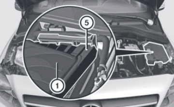
Engine Compartment Fuse Box
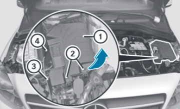
- Open the hood.
- Use a dry cloth to remove any moisture from the fuse box.
- To open: unclip hood release cable (4) from bracket (3).
- Open retaining clamps (2).
- Fold cover (1) up in the direction of the arrow and remove it.
- To close: check whether the seal is seated correctly in cover (1).
- Insert cover (1) at the back into openings (5) on the fuse box.
- Slide hood release cable (4) to the side and hold if necessary.
- Fold-down cover (1).
- Clip hood release cable (4) into bracket (3).
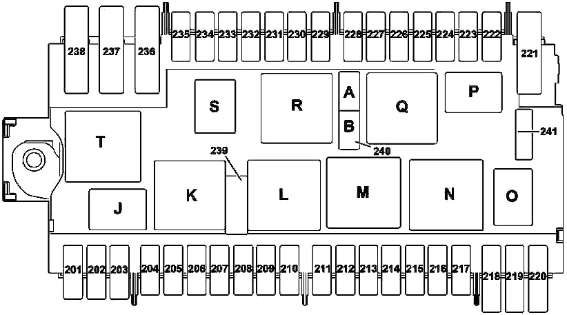
| № | Fused function | A |
|---|---|---|
| 201 | Alarm siren | 5 |
| 202 | Stationary heater control unit | 20 |
| Electric Drive (W242): Park pawl control unit circuit 87 relay | 5 | |
| 203 | LED headlamp: Right front lamp unit | 15 |
| Electric Drive (W242): Powertrain control unit | 5 | |
| 204 | Electronic Stability Program control unit | 25 |
| 205 | Left fanfare horn | 15 |
| Right fanfare horn | ||
| 206 | Valid for engine 651: CDI control unit | 5 |
| Valid for engine 607: Powertrain control unit | ||
| Electric Drive (W242): | ||
| Brake booster vacuum pump relay | ||
| Circuit relay87M | ||
| 207 | Valid for diesel engine: Circuit relay87M | 5 |
| Electric Drive (W242): | ||
| High-voltage battery cooling shutoff valve | ||
| Park pawl control unit | ||
| 208 | Valid for engine 133, 607: Circuit 87 relay | 7.5 |
| Electric Drive (W242): Fan motor | 5 | |
| 209 | LED headlamp: Left front lamp unit | 15 |
| Electric Drive (W242): Spare | - | |
| 210 | Heated windshield relay | 5 |
| as of 03.11.2014 except (Canada version): Starter front-end relay | 5 | |
| 211 | Natural Gas Drive (W242): CNG control unit | 7.5 |
| Electric Drive (W242): Heater circuit circulation pump | 15 | |
| 212 | Valid for engine 133, 270: Connector sleeve, circuit 87M3 | 15 |
| Valid for engine 651: | ||
| Vent line heater element | ||
| Coolant thermostat heating element | ||
| Exhaust gas recirculation cooler bypass switchover valve | ||
| Valid for engine 607 (Emissions standard EU5): | ||
| Oxygen sensor upstream of catalytic converter | ||
| Boost pressure positioner | ||
| Valid for engine 607 (Emissions standard EU6): Oxygen sensor upstream of catalytic converter | ||
| Valid for engine 607: CDI control unit | ||
| Electric Drive (W242): Electric drive and charger coolant pump | ||
| 213 | Valid for engine 133, 270, 651: Connector sleeve, circuit 87 M2e | 15 |
| Valid for engine 607 (Emissions standard EU5): | ||
| Camshaft Hall sensor | ||
| CDI control unit | ||
| Quantity control valve | ||
| Valid for engine 607 (Emissions standard EU6): | ||
| Oxygen sensor downstream of catalytic converter | ||
| CDI control unit | ||
| Electric Drive (W242): Battery cooling system coolant pump 1 | ||
| 214 | Valid for engine 133, 270, 651: Connector sleeve, circuit 87 M4e | 10 |
| Electric Drive (W242): Battery cooling system coolant pump 2 | 15 | |
| 215 | Valid for gasoline engine: | 20 |
| Cylinder 1 ignition coil | ||
| Cylinder 2 ignition coil | ||
| Cylinder 3 ignition coil | ||
| Cylinder 4 ignition coil | ||
| Valid for engine 651: Quantity control valve | ||
| Valid for engine 607: | ||
| CDI control unit | ||
| Boost pressure positioner | ||
| Quantity control valve | ||
| Electric Drive (W242): | 5 | |
| Thermal management control unit | ||
| Gateway powertrain control unit | ||
| Electric Drive (W242) as of 03.11.2014: High-voltage power distributor | ||
| 216 | Valid for gasoline engine: ME-SFI control unit | 5 |
| Valid for engine 607: Powertrain control unit | ||
| 217 | Valid with transmission 724: Dual clutch transmission fully integrated transmission control unit | 25 |
| 218 | Electronic Stability Program control unit | 5 |
| 219 | Electric Drive (W242): Park pawl control unit | 5 |
| 220 | Transmission cooling coolant circulation pump | 10 |
| 221 | Electric Drive (W242): Vacuum pump | 40 |
| 222 | Electric Drive (W242): Electrical refrigerant compressor | 7.5 |
| 223 | Spare | - |
| 224 | DISTRONIC electric controller unit | 7.5 |
| COLLISION PREVENTION ASSIST controller unit | ||
| 225 | Electric Drive (W242): Powertrain control unit | 5 |
| 226 | Natural Gas Drive (W242): CNG control unit | 5 |
| Electric Drive (W242): | ||
| Charger control unit | ||
| Power electronics control unit | ||
| 227 | Electric Drive (W242): Power electronics control unit | 5 |
| 228 | Electric Drive (W242): Electric vehicle sound generator | 5 |
| 229 | Left front lamp unit | 5 |
| 230 | Electronic Stability Program control unit | 5 |
| 231 | Right front lamp unit | 5 |
| 232 | Headlamp control unit | 15 |
| 233 | Spare | - |
| 234 | Valid for engine 607: Powertrain control unit | 5 |
| Electric Drive (W242): High-voltage power distributor | 10 | |
| 235 | Valid for engine 607: | 7.5 |
| Fan motor | ||
| Radiator shutters actuator | ||
| Valid for engine 133: | 7.5 | |
| Charge air cooler circulation pump | ||
| Charge air cooler circulation pump | ||
| 236 | SAM control unit | 40 |
| 237 | Electronic Stability Program control unit | 40 |
| 238 | Heated windshield | 50 |
| 239 | Wiper speed 1/2 relay | 30 |
| 240A | Starter circuit 50 relay | 25 |
| Electric Drive (W242): Powertrain control unit | 7.5 | |
| 240B | Circuit 15 relay (not latched) | 25 |
| 241 | Electric Drive (W242): High-voltage PTC heater | 7.5 |
| J | Fanfare horn relay | |
| K | Wiper speed 1/2 relay | |
| L | Windshield wiper ON/OFF relay | |
| M | Starter circuit 50 relay | |
| Electric Drive (W242): Circuit 87C relay | ||
| N | Circuit relay87M | |
| O | ECO start/stop: Transmission cooling coolant circulation pump relay | |
| Electric Drive (W242): Park pawl control unit circuit 87 relay | ||
| P | Backup relay (F58kP) | |
| Q | Circuit 15 relay (not latched) | |
| Electric Drive (W242): Brake booster vacuum pump supply relay (F58kQ) | ||
| R | Circuit 15 relay | |
| S | Circuit 87 relay | |
| T | Heated windshield relay | |
Advertisements
Front electrical prefuse box
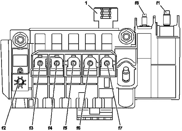
| № | Fused function | A |
|---|---|---|
| 1 | Alternator | 300 |
| Electric Drive (W242): DC/DC converter control unit | 400 | |
| 2 | Vehicle interior fuse box | 200 |
| Valid for diesel engine: Vehicle interior fuse box | 250 | |
| 3 | Electrical power steering control unit | 100 |
| 4 | SAM control unit | 40 |
| 5 | Fan motor | 80 |
| 6 | Valid for engine 607: Fuel preheating control unit | 70 |
| 7 | Valid for engine 607 (Emissions standard EU5): DPF regeneration heater booster control unit | 125 |
| 8 | Valid for engine 607, 651: Glow output stage | 100 |
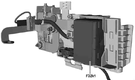
| F32k1 | Decoupling relay | |
Advertisements