
Advertisements
Fuse box diagram (fuse layout), location, and assignment of fuses and relays Mercedes-Benz A-Class A150, A160, A170, A180, A200 (W169) (2004, 2005, 2006, 2007, 2008, 2009, 2010, 2011, 2012).

Checking and Replacing Fuses
The fuses in your vehicle serve to close down faulty circuits. If a fuse blows, all the components on the circuit and their functions stop operating. If a fuse has blown, the inside element will be melted. Blown fuses must be replaced with fuses of the same rating, which you can recognize by the color and value. The fuse ratings are listed in the fuse allocation chart.
If a newly inserted fuse also blows, have the cause traced and rectified at a qualified specialist workshop, e.g. an authorized Mercedes-Benz Center.
Notice
- Before changing a fuse, secure the vehicle against rolling away and switch off all electrical consumers.
- Always disconnect the battery before servicing high current fuses.
- Always replace faulty fuses with the specified new fuses having the correct amperage. If you manipulate or bridge a faulty fuse or if you replace it with a fuse with a higher amperage, the electric cables could be overloaded. This could result in a fire. There is a risk of an accident and injury.
- Only use fuses that have been approved for Mercedes-Benz vehicles and which have the correct fuse rating for the system concerned. Only use fuses marked with an “S”. Otherwise, components or systems could be damaged.
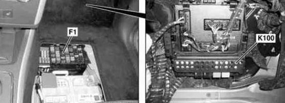
Passenger Compartment Fuse Box Diagram
The main fuse box is located in the front-passenger footwell in front of the seat.
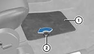
To access:
- Remove the footmats.
- Turn retaining screw (2) anti-clockwise using a coin for example.
- Raise cover (1) and remove it.
- Remove the cover mat from the battery.
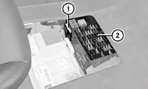
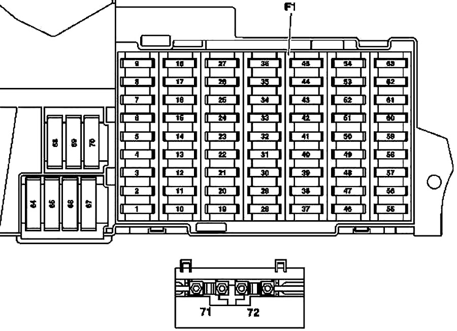
- Fuse allocation chart
- Fuse box
| № | Fused function | A |
|---|---|---|
| 1 | Stop light switch | 10 |
| Valid for code (U62) Light and vision package: | 5 | |
| Stop light switch | ||
| 2 | Heated rear window | 25 |
| 3 | Instrument cluster | 7.5 |
| EIS [EZS] control unit | ||
| 4 | EIS [EZS] control unit | 15 |
| Electric steering lock control unit | ||
| 5 | Valid without code (580) Automatic air conditioning and without code (581) Comfort automatic air conditioning: | 7.5 |
| HEAT control and operating unit | ||
| Valid for code (580) Automatic air conditioning: | ||
| AAC [KLA] control and operating unit | ||
| Valid for code (581) comfort automatic air conditioning: | ||
| Comfort AAC [KLA] control and operating unit | ||
| 6 | Left fanfare horn | 15 |
| Right fanfare horn | ||
| 7 | Fuel pump relay | 25 |
| Valid for model 169.090: | 5 | |
| DC/DC converter control unit | ||
| 8 | Overhead control panel control unit | 25 |
| 9 | ESP and BAS control unit | 40 |
| 10 | Blower regulator/interior wiring harness connector | 40 |
| 11 | Valid for engine 266: | 30 |
| Circuit 87 relay, engine | ||
| Valid for engine 640: | 40 | |
| Circuit 87 relay, engine | ||
| 12 | Steering column module | 5 |
| Multifunction steering wheel | ||
| 13 | Left front door control unit | 25 |
| 14 | Right front door control unit | 25 |
| 15 | ESP and BAS control unit | 25 |
| 16 | Data link connector | 10 |
| PTS control unit | ||
| 17 | Rotary light switch | 5 |
| 18 | Valid for transmission 711, 716: | 7.5 |
| Backup lamp switch | ||
| Valid for model 169.090: | ||
| A/C compressor control unit | ||
| BKGN Energy monitoring control unit | ||
| Vacuum pump 1 control unit | ||
| Vacuum pump 2 control unit | ||
| 19 | Micromechanical turn rate sensor AY pickup | 5 |
| 20 | Restraint systems control unit | 7.5 |
| 21 | Starter relay | 30 |
| 22 | Instrument cluster | 7.5 |
| 23 | Washer nozzle heating | 7.5 |
| Valid for engine 640 as of 1.9.08: | 20 | |
| Fuel filter condensation sensor with heating element | ||
| 24 | Electric power steering (ES) control unit | 7.5 |
| 25 | Stop light switch | 7.5 |
| ESp and BAS control unit | ||
| 26 | Valid for transmission 722: | 7.5 |
| Electronic selector lever module control unit | ||
| 27 | Valid for transmission 722: | 10 |
| CVT (continuously variable automatic transmission) control unit | ||
| 28 | Rotary light switch | 5 |
| 29 | SAM control unit | 30 |
| 30 | Circuit 87F relay | 25 |
| 31 | Central gateway control unit (vehicles up to 30.11.05) | 5 |
| Rotary light switch | ||
| Automatic light switch daylight sensor | ||
| Rain/light sensor | ||
| 32 | Valid for engine 266: | 7.5 |
| ME-SFI [ME] control unit | ||
| Valid for model 169.090: | ||
| Energy monitoring control unit | ||
| 33 | Radio | 15 |
| Radio and navigation unit | ||
| COMAND operating, display and control unit (Japan) | ||
| 34 | Left rear door control unit | 25 |
| 35 | Right rear door control unit | 25 |
| 36 | Cell phone separation point | 7.5 |
| Trailer control unit | ||
| Trailer control unit | 10 | |
| PTS control unit | ||
| 37 | Restraint systems control unit | 7.5 |
| Front passenger seat occupied recognition sensor | ||
| Front passenger seat occupied and child seat recognition sensor | ||
| 38 | Front cigar lighter with ashtray illumination | 25 |
| 39 | Wiper motor | 25 |
| 40 | Overhead control panel control unit | 7.5 |
| Roof motor | 25 | |
| 41 | Liftgate wiper motor | 15 |
| 42 | Glove compartment illumination with switch | 7.5 |
| Left and right vanity mirrors illumination | ||
| Footwell illumination switch (driving school package) | ||
| Pedal operation monitor switch (driving school package) | ||
| VICS+ETC voltage supply separation point (Japan) | ||
| 43 | Valid for engine 266: | 15 |
| Terminal 87M1 e connector sleeve | ||
| Valid for engine 640: | 7.5 | |
| Terminal 87M1e connector sleeve | ||
| Valid for model 169.090: | 20 | |
| Vacuum pump 1 control unit | ||
| 44 | Valid for engine 266: | 15 |
| Terminal 87M2e connector sleeve | ||
| Valid for engine 640: | 20 | |
| Terminal 87M2e connector sleeve | ||
| 45 | Valid for engine 640: | 25 |
| CDI control unit | ||
| Valid for model 169.090: | ||
| Vacuum pump 2 control unit | ||
| 46 | Telephone control unit, (Japan) | 7.5 |
| E-net compensator | ||
| Universal Portable CTeL Interface (UPCI [UHI]) control unit | ||
| Bass module speaker (Japan) | 25 | |
| Amplifier for sound system | 40 | |
| Valid for model 169.090: | 5 | |
| Charging control unit | ||
| 47 | Telephone control unit, (Japan) | 7.5 |
| Universal Portable CTEL Interface (UPCI [UHI]) control unit | ||
| Cell phone separation point | ||
| Voice control system (VCS [SBS]) control unit | ||
| Valid for model 169.090: | ||
| Charger 1 | ||
| 48 | ATA [EDW]/tow-away protection/interior protection control unit | 7.5 |
| Alarm signal horn with additional battery | ||
| Valid for model 169.090: | ||
| Charger 2 | ||
| 49 | Upper control panel control unit | 25 |
| Left front seat heated cushion | ||
| Left front backrest heated cushion | ||
| Right front seat cushion heater element | ||
| Right front backrest seat cushion heater element | ||
| 50 | CD changer | 7.5 |
| Media interface control unit | ||
| Digital TV tuner | ||
| Digital Audio Broadcasting control unit | ||
| VICS+ETC voltage supply separation point (Japan) | ||
| Valid for government vehicles: | 30 | |
| Roof light bar | ||
| Circuit 30 connector sleeve | ||
| 51 | Valid for model 169.090: | 10 |
| Cooling fan | ||
| Low temperature coolant pump | ||
| 52 | VICS+ETC voltage supply separation point (Japan) (vehicles up to 31.5.06) | 5 |
| Valid for model 169.090: | ||
| Electric drive control unit | ||
| Spare (vehicles as of 1.6.06) | 7.5 | |
| Emergency call system control unit (USA) (vehicles up to 31.5.06) | 7.5 | |
| 53 | Rear cigar lighter with ashtray illumination | 30 |
| Interior socket | ||
| 54 | Amplifier for sound system | 25 |
| Bass module speaker | ||
| Valid for model 169.090: | 5 | |
| Electric drive control unit | ||
| 55 | Left front lamp unit (Bi-xenon) | 7.5 |
| Right front lamp unit (Bi-xenon) | ||
| Left front lamp unit (Hi-xenon) | 10 | |
| 56 | Spare | 10 |
| Right front lamp unit (Hi-xenon) | 10 | |
| 57 | Trailer hitch socket (13-pin) (vehicles as of 1.6.05) | 15 |
| Audio gateway control unit (Japan) (vehicles up to 31.5.05) | 25 | |
| SDAR control unit | 7.5 | |
| Emergency call system control unit (USA) | ||
| 58 | Trailer control unit | 25 |
| Valid for model 169.090: | ||
| Vehicle gateway control unit | ||
| 59 | Trailer control unit (vehicles up to 31.5.05) | 20 |
| Trailer hitch socket (13-pin) (vehicles as of 1.6.05) | ||
| Valid for model 169.090: | 5 | |
| Battery management system control unit 1 | ||
| 60 | Driver seat connector block | 20 |
| 61 | Front passenger seat connector block | 20 |
| 62 | Circuit 15 relay (2) (SA: xenon, cell phone) | 25 |
| 63 | Spare (vehicles up to 31.5.05) | - |
| Audio gateway control unit (Japan) (vehicles as of 1.6.05) | 25 | |
| Valid for government vehicles: | ||
| Roof light bar | ||
| Emergency call system control unit (USA) (vehicles as of 1.6.05) | 7.5 | |
| SDAR control unit | ||
| Valid for model 169.090: | 5 | |
| Battery management system control unit 2 | ||
| 64 | Valid for engine 266: | 40 |
| Air pump relay | ||
| Valid for engine 640: | 80 | |
| Engine wiring harness/engine compartment connector | ||
| Glow time output stage | ||
| 65 | Electric power steering (ES) control unit | 80 |
| 66 | SAM control unit | 60 |
| 67 | Circuit 15R relay (2) (SE) | 50 |
| 68 | Valid for engine 266.920 and engine 266.940 with transmission 722: | 50 |
| AAC with integrated control additional fan motor | ||
| Valid for engine 640.940, 640.941, 266.960, 266.980 and for engine 266.920, 266.940 with (Trailer hitch): | 60 | |
| AAC with integrated control additional fan motor | ||
| 69 | Circuit 15R relay (1) | 50 |
| 70 | Circuit 15 relay (1) | 60 |
| 71 | Valid for engine 640: | 150 |
| PTC heater booster | ||
| 72 | Circuit 30 connector sleeve | 60 |
| Special vehicle multifunction control unit (SVMCU [MSS]) (Taxi) |
Advertisements
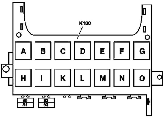
Relay Module
| № | Fused function | A |
|---|---|---|
| 80 | Reserved for special-purpose vehicles | 30 |
| 81 | Reserved for special-purpose vehicles | 30 |
| 82 | Reserved for special-purpose vehicles | 30 |
| 83 | Reserved for special-purpose vehicles | 30 |
| A | Circuit 15R relay (2) (SA) | |
| B | Circuit 15R relay (1) | |
| C | Fanfare horn relay | |
| D | Heated rear window relay | |
| E | Wiper stage 1/2 relay | |
| F | Wiper ON/OFF relay | |
| G | Circuit 15 relay (1) | |
| H | Backup relay | |
| I | Air pump relay | |
| K | Fuel pump relay | |
| L | Engine circuit 87 relay | |
| M | Starter relay | |
| N | Circuit 87F relay | |
| O | Circuit 15 relay (2) (SA: xenon, cell phone) | |
Advertisements