
Advertisements
Fuse box diagram (fuse layout), location, and assignment of fuses Mazda CX-7 (2006, 2007, 2008, 2009).

Checking and Replacing Fuses
Your vehicle’s electrical system is protected from overloading by fuses. If any lights, accessories, or controls in the vehicle don’t work, inspect the appropriate circuit protector. If a fuse has blown, the inside element will be melted.
In case if you have no spare fuses, borrow one of the same rating from a circuit not essential to vehicle operation, such as the ROOM or OUTLET circuit.
If the same fuse blows again, avoid using that system and consult an Authorized Mazda Dealer as soon as possible.
Notice
- Always switch off the ignition system and the affected electrical circuit before replacing a fuse.
- Always disconnect the battery before servicing high current fuses.
- Never use a fuse of a higher amperage rating than that indicated, or use any other object in place of a fuse, even as a temporary fix. This can cause extensive damage or even fire.
Passenger Compartment Fuse Box
If the electrical system does not work, first inspect the fuses on the driver’s side.
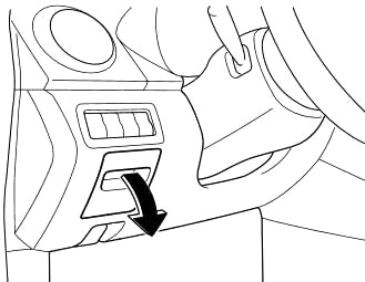
- Turn off the ignition switch and other switches.
- Open the fuse panel cover.
- Pull the fuse straight out with the fuse puller provided on the inside of the cover for the fuse panel and the fuse block cover inside of the engine compartment.
- Inspect the fuse and replace it if it’s blown.
- Insert a new fuse of the same amperage rating, and make sure it fits tightly.
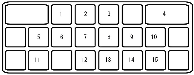
| № | Description | A | Protected component |
|---|---|---|---|
| 1 | OUTLET | 15 | Accessory Socket |
| 2 | OUTLET 2 | 15 | Accessory Socket |
| 3 | P.MIR | 7.5 | Power control mirror |
| 4 | WIPER | 30 | Windshield wiper and washer |
| 5 | M.DEF | 7.5 | Mirror defroster * |
| 6 | ENG BAR 3 | 7.5 | Air flow sensor, EGR control valve |
| 7 | P.W1ND | 15 | Power windows |
| 8 | A/B | 7.5 | Advance Restraint System |
| 9 | ENGINE | 15 | Engine control system |
| 10 | METER | 10 | Instrument cluster |
| 11 | ROOM | 15 | Audio system, Overhead light |
| 12 | ILLUMI | 10 | Dashboard illumination |
| 13 | SEAT | 20 | Seat warmer * |
| 14 | A/C | 10 | Air conditioner * |
| 15 | R.WIP | 10 | Rear window wiper and washer |
| * Some models | |||
Advertisements
Engine Compartment Fuse Box
If the headlights or other electrical components do not work and the fuses in the cabin are normal, inspect the fuse block under the hood. If a fuse is blown, it must be replaced.
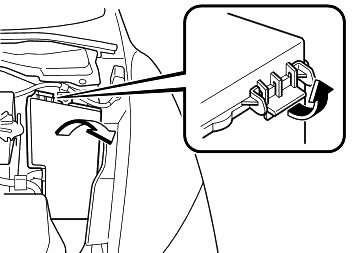
Follow these steps:
- Turn off the ignition switch and all other switches.
- Remove the fuse block cover.
- Pull the fuse straight out with the fuse puller provided on the inside of the engine compartment fuse block cover.
- If any fuse but the MAIN fuse is blown, replace it with a new one of the same amperage rating.
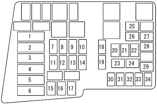
| № | Description | A | Protected component |
|---|---|---|---|
| 1 | IGN 2 | 40 | Ignition system |
| 2 | BLOWER | 40 | Blower motor |
| 3 | BTN | 60 | For protection of various circuits |
| 4 | FAN 2 | 40 | Cooling fan |
| 5 | IGN 1 | 40 | Ignition system |
| 6 | FAN 1 | 40 | Cooling fan |
| 7 | P.SEAT | 40 | Power seat * |
| 8 | INJ | 30 | Injector |
| 9 | ROOF | 20 | Moonroof * |
| 10 | BOSE | 30 | Bose audio system |
| 11 | ENGINE | 30 | Engine control system |
| 12 | D.LOCK | 20 | Power door locks |
| 13 | P.WIND | 30 | Power windows |
| 14 | FUEL | 30 | Fuel pump |
| 15 | ABS 1 | 40 | ABS |
| 16 | ABS 2 | 20 | ABS |
| 17 | DSC | 7.5 | DSC |
| 18 | FOG | 20 | Fog lights * |
| 19 | DEF | 30 | Rear window defroster |
| 20 | TNS | 15 | Parking lights, License plate lights, Illuminated entry system |
| 21 | A/C | 10 | Air conditioner * |
| 22 | ETC | 20 | Accelerator position sensor |
| 23 | H/LHI | 15 | Headlight leveling * |
| 24 | DRL | 15 | DRL * |
| 25 | H/L LO RH | 15 | Headlight low beam (RH) |
| 26 | H/L LO LH | 15 | Headlight low beam (LH) |
| 27 | ENG BAR 2 | 7.5 | PCM |
| 28 | ECM | 10 | Engine control system |
| 29 | ENG BAR 1 | 15 | Air flow sensor, EGR control valve |
| 30 | P.W1ND 2 | 20 | Power windows |
| 31 | STOP | 10 | Brake lights |
| 32 | HORN | 20 | Horn |
| 33 | ENGB+ | 25 | PCM |
| 34 | HAZARD | 10 | Hazard warning flashers. Turn signals |
| * Some models | |||
Advertisements