Advertisements
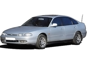
Fuse box diagram (fuse layout), location, and assignment of fuses and relays Mazda 626 and MX-6 (GE) (1991, 1992, 1993, 994, 1995, 1996, 1997).

Checking and Replacing Fuses
Your vehicle’s electrical system is protected from overloading by fuses. If any lights, accessories, or controls in the vehicle don’t work, inspect the appropriate circuit protector. If a fuse has blown, the inside element will be melted.
In case if you have no spare fuses, borrow one of the same rating from a circuit not essential to vehicle operation, such as the MIRROR, RADIO or CIGAR circuit.
If the same fuse blows again, avoid using that system and consult an Authorized Mazda Dealer as soon as possible.
Notice
- Always switch off the ignition system and the affected electrical circuit before replacing a fuse.
- Always disconnect the battery before servicing high current fuses.
- Never use a fuse of a higher amperage rating than that indicated, or use any other object in place of a fuse, even as a temporary fix. This can cause extensive damage or even fire.
Passenger Compartment Fuse Box Diagram
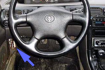
The fuses are located below the driver’s side of the dashboard near the door.


| № | Name | A | Function |
|---|---|---|---|
| 1 | STOP | 20 | Brake Lights |
| High Mounted Brake Light | |||
| Horns | |||
| Cruise Control System | |||
| Shift-Lock System | |||
| 2 | ROOM | 15 | Courtesy Lights |
| Vanity Mirror Lights | |||
| Trunk Compartment Light | |||
| Audio System | |||
| Power Door Locks | |||
| Power Door Locks (with keyless entry system) | |||
| Power Antenna | |||
| Theft-Deterrent System | |||
| Central Processing System | |||
| Instrument Cluster | |||
| EC-AT Control System | |||
| Spot Lights | |||
| Interior Light | |||
| Ignition Key Illumination | |||
| Engine Control System | |||
| Ignition System | |||
| 3 | DOOR LOCK | 30 | Power Door Locks |
| Power Door Locks (with keyless entry system) | |||
| 4 | RADIO | 15 | Audio System |
| Cigarette Lighter | |||
| Power Antenna | |||
| Power Outside Mirrors | |||
| 5 | SUNROOF | 15 | Sliding Sunroof |
| 6 | TURN | 15 | Turn and Hazard Warning Lights |
| Air Bag System | |||
| 7 | POWER SEAT | 30 | Power Seat |
| 8 | METER | 15 | Back-Up Lights |
| Data Link Connector | |||
| Instrument Cluster | |||
| EC-AT Control System | |||
| Theft-Deterrent System | |||
| Central Processing System | |||
| Power Antenna | |||
| Cruise Control System | |||
| Shift-Lock System | |||
| Engine Control System (FS) | |||
| ATX Ignition System (FS) | |||
| 9 | HAZARD | 15 | Turn and Hazard Warning Lights |
| 10 | ENGINE | 15 | Engine Control System |
| MTX Fuel Control System (FS) | |||
| Ignition System | |||
| Starting System | |||
| EC-AT Control System (FS) | |||
| Coolant Fan System | |||
| Heater and Air Conditioner | |||
| Antilock Brake System | |||
| Air Bag System | |||
| Rear Window Defroster | |||
| 11 | POWER WINDOW | 30 | Power Windows |
| 12 | HEAD CLEANER | 20 | Headlight Cleaner |
| 13 | WIPER | 20 | Windshield Wiper and Washer |
| Heater and Air Conditioner | |||
| Condenser Fan System | |||
| Daytime Running Lights (DRL) | |||
| Engine Control System (FS) | |||
| EC-AT Control System (FS) | |||
| Ignition System (FS) | |||
| 14 | REAR WIPER | 20 | Rear Wiper & Washer |
| 15 | SPARE | 15 | Spare |
Advertisements
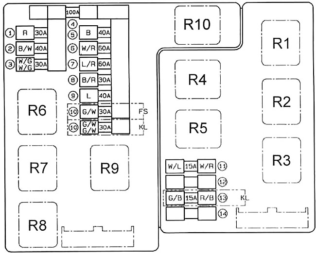
Engine Compartment Fuse Box Diagram

| № | Name | A | Function |
|---|---|---|---|
| 1 | HEAD | 30 | Headlight |
| Daytime Running Lights (DRL) | |||
| 2 | DEFOG | 40 | Rear Window Defroster |
| 3 | EGI INJ | 30 | Charging System |
| Engine Control System | |||
| EC-AT Control System (FS) | |||
| ATX Ignition System (FS) | |||
| ATX Fuel Control System (FS) | |||
| Fuel Control System (KL) | |||
| Ignition System (KL) | |||
| 4 | MAIN | 100 | Charging System |
| Fuse №: 5, 6, 7, 8, 9, 10 | |||
| 5 | IG KEY | 40 | Ignition Switch (Fuse №: 5, 6, 8, 10, 11, 13 (passenger compartment fuse box)) |
| 6 | BTN | 60 | Fuse №: 11 |
| Fuse №: 1, 2, 3, 7, 9 (passenger compartment fuse box) | |||
| 7 | ABS | 60 | Antilock Brake System |
| 8 | COOLING FAN | 30 | Coolant Fan System |
| 9 | HEATER | 40 | Heater and Air Conditioner |
| 10 | AIR-COND | 30 | Condenser Fan System |
| 11 | TAIL | 15 | Tail Lights |
| Parking Lights | |||
| Illumination Lights | |||
| License Plate Light | |||
| Front Side Marker Lights | |||
| Rear Side Marker Lights | |||
| Glove Box Light | |||
| 12 | * | ||
| 13 | FOG | 15 | Front Fog Lights |
| 14 | * | ||
| R1 | Starter Interrupt Relay | ||
| Headlight High Relay | |||
| R2 | Main Relay | ||
| R3 | Fuel Pump Relay | ||
| R4 | Horn Relay | ||
| R5 | Daytime Running Lights (DRL) Relay | ||
| R6 | Cooling Fan Relay №3 | ||
| R7 | Cooling Fan Relay №2 | ||
| R8 | Cooling Fan Relay №1 | ||
| R9 | A/C Relay | ||
| R10 | A/C Relay | ||
Relays

| № | Relay |
|---|---|
| R1 | Blower Relay |
| R2 | Headlight Relay |
| R3 | Rear Window Defroster Relay |
| R4 | TNS Relay |
| R5 | Condenser Fan High Relay №2 |
| R6 | Condenser Fan Low Relay |
| R7 | Condenser Fan High Relay №1 |
Advertisements
